(Mar, 2012)
Compact CWE Series Installation, Operation & Maintenance Manual
ir Technology Systems, Inc.
2-12
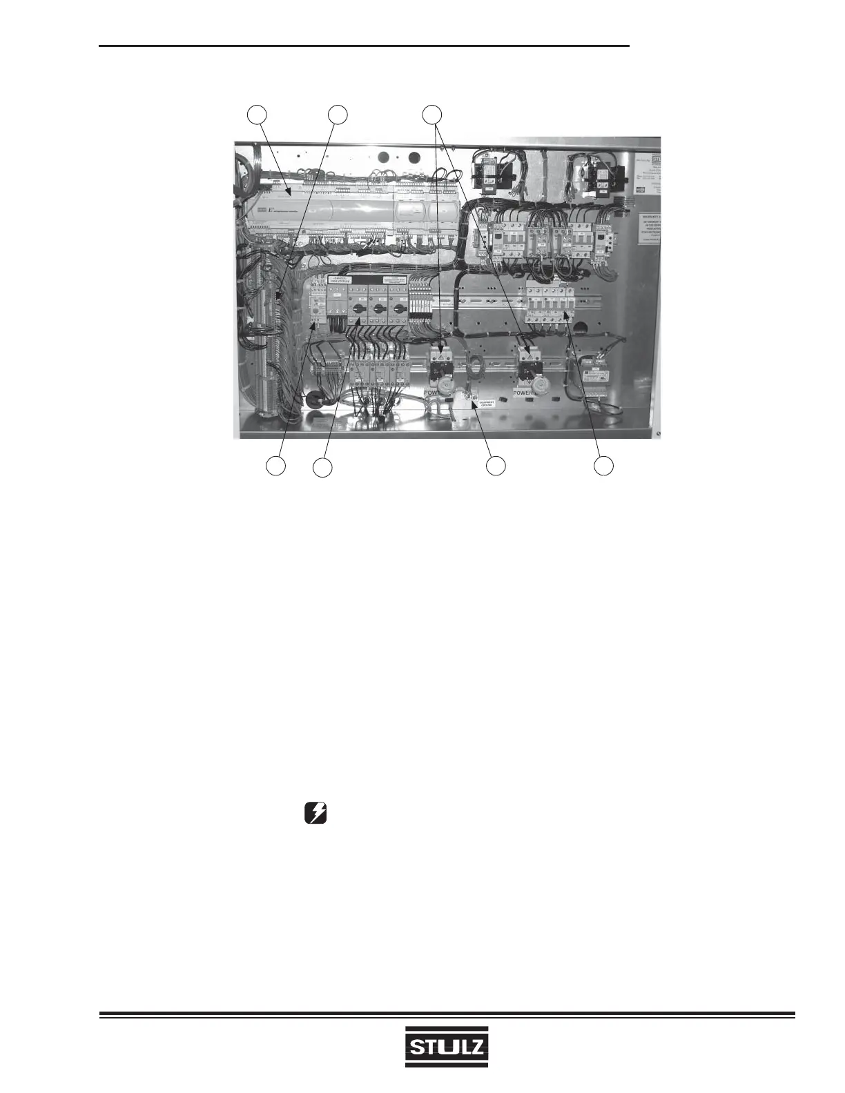
Figure 18- Electric Box
1 2 3
5
6
47
The size of the electric box and location of components
vary according to the Compact CWE model. Figure 18
shows a sample electric box layout and identifi es the
major components. The numbered call-outs in Figure
18 coincide with the numbered items listed below:
1. Control I/O Board
2. Interface Terminals
3. Power Service Disconnect Switches
(Shown with Optional Dual Power Switches)
4. Control Circuit Breakers
5. Ground Lug
6. Power Switches/Motor Starter Protectors
(Quantity Varies)
7. Water Detector Control Module (Optional)
CAUTION
Prior to unit operation, an adequate unit-to-
earth ground must be connected to the unit.
2.8.2 Controls
SATS offers a wide range of control features to solve
your air conditioning control/alarm requirements.
The Compact CWE system is furnished with a
microprocessor controller with a user interface display
panel. If the display is mounted on the unit (standard),
no utility connection is required. As an option, a factory
assembled remote mounted display panel may be
provided. In such a case, a cable harness is provided
to interconnect the display to the controller. Refer
to the electrical drawing provided for details on all
interconnecting fi eld wiring.