(Mar, 2012)
Compact CWE Series Installation, Operation & Maintenance Manual
ir Technology Systems, Inc.
4-2
NOTE
The yellow LED may illuminate during initial
start-up but it doesn’t necessarily mean the
cylinder needs to be replaced.
Refer to Section 4.3.1.3 and the humidifi er operator’s
manual supplied under separate cover for detailed
instructions on changing the cylinder.
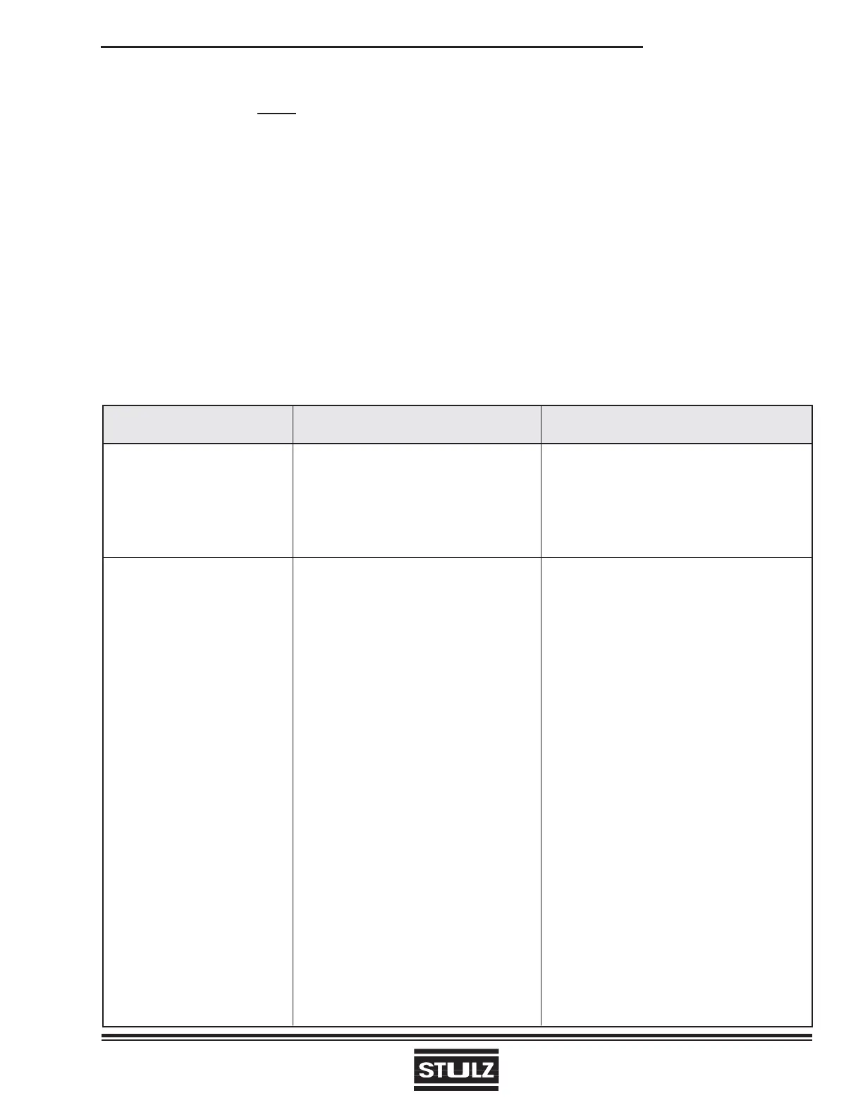
SYMPTOM PROBABLE CAUSE RECOMMENDATION
Chilled Water Valve Fails a. Temperature setpoint too high Adjust to correct temperature setting
to Open or Close
b. No control power to the valve Valve actuator is wired incorrectly. Check
wiring schematic and rewire if required.
c. Actuator failed Replace actuator
EC Fan(s) Fail to Start a. Power failure Check main voltage power source
input cable
b. Motor starter protector tripped Reset motor starter protector and check
amperage of motor. Compare to setting
on motor starter protector and adjust to
correct FLA.
c. Control transformer circuit Check for short circuit or ground fault;
breaker tripped if none reset circuit breaker
d. Condensate overfl ow switch open 1. Ensure unit is level
2. Check that condensate pan is draining.
e. Defective contactor Repair or replace
f. No control signal to fan(s) Check the Control I/O Board for a 0-10
VDC control signal to the fan(s). Refer
to the electric drawing to determine the
correct I/O board terminal numbers. This
must done within 15 seconds of turning
the disconnect switch “On” or the controller
will go into “Air Proving Alarm” mode.
g. EC fan’s internal overheat protection Determine the cause of the interruption and
interrupted fan motor operation correct. Possible causes are:
1. Blocked rotor
2. Low supply voltage > 5 seconds
3. Loss of phase > 5 seconds
After causes 1, 2, and 3 are corrected, the
motor will automatically reset.
(Continued on next page)
4.1.1.7 Condensate Pump
The condensate pump should be inspected semi-
annually and cleaned. Ensure that the fl oat works
freely. Wipe the fl oat with a wet cloth and detergent to
remove debris. Clean the tank bottom. Check that the
discharge line is open and water can pass through it
freely.
4.2 Troubleshooting
Turn off all power to the unit before conducting any troubleshooting procedures unless the procedure spe-
cifi cally requires the system to operate. For troubleshooting purposes, the system may be operated with
the doors open by using channel lock pliers to turn the shaft of the main power disconnect switch to the
“On” position. NOTE: When the switch is turned on, high voltage will be present inside the cabinet.
Exercise caution to prevent injury. Keep hands, clothing and tools clear of the electrical terminals and rotat-
ing components. Ensure that your footing is stable at all times.