BA C7000 for EC Tower | EN | 01-2019 | 1000755
32
t
t
t
t
I
O
I
O
j = j
P
+ j
I
+ j
D
j = 3 + 5 + (- 2)
j = 6%
t
t
I
O
I factor
Measured
value
Setpoint
D factor
Measured
value
Setpoint
To clarify the principle influence of the I/D
part, an open control circuit is depicted
here.
In reality, the control circuit is closed and
the change to the output variable influences
the input variable (measured value).
I: Input variable, return air tempera-
ture/supply air temperature, in
general, condensation pressure for
G valve.
O: Output variable, speed, for valves of
the degree of openness
PID control
For the following components, a PID control can be set, consisting of a P factor, I
factor and D factor:
- ICC - Pump for CPP units
- HGBP valve - Fan for differential temperature control
- G valve - Air dampers for DFC² control
- GE/CW valve - Condenser fan for DFC² control
- EC tower
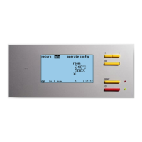
P factor
Via the P factor, you can set the ratio of the output variable to the input variable dif-
ference (measured value minus setpoint).
For each deviation from the setpoint, there is a fixed output value for the component,
which should counteract the deviation.
A characteristic of the proportional regulation is a permanent deviation of the input
variable from the setpoint as long as there is a disturbance variable.
As an example, the individual parts (P, I, and D part) shall be calculated for a setpoint
deviation of DT = 0.3 K for the GE/CW valve.
Example: Tsetp = 24 °C
Tactual = 24.3 °C
j
P
= K
P
•DT• k
K
P
j
P
= 10 • 0.3 • 1
j
P
= 3 (degree of openness in %)
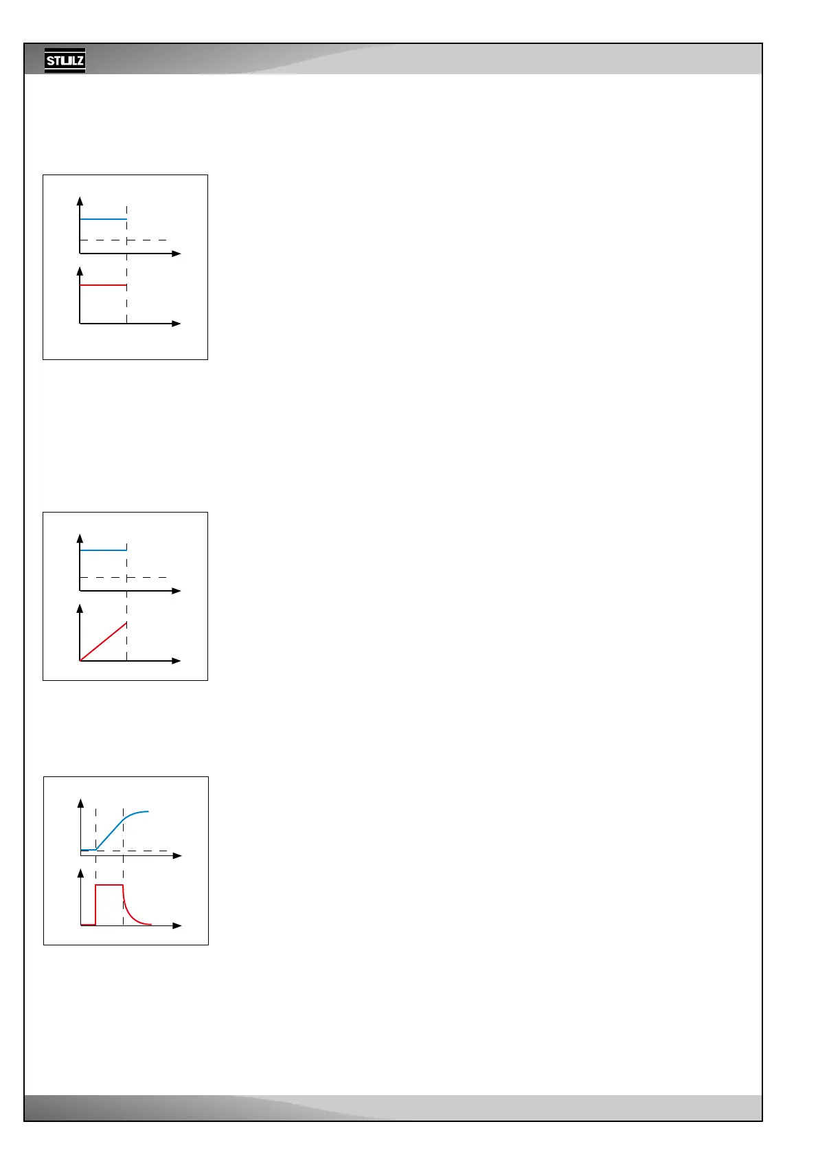
I factor
The integral part of the control is adjusted with the I factor. The integral part reacts to
a difference between the measured value and setpoint with an output variable that is
constantly rising. The larger the difference, the faster the output variable increases.
The I part helps to avoid a constant setpoint deviation.
The sooner the control takes effect, the larger the chosen I factor can be.
Example: for ICC, if the supply air control has been set.
The more storage elements (e.g. such as big room volumes in the case of return air
control) there are in the control circuit, the smaller the chosen I-factor has to be in to
prevent the control circuit from oscillating.
Example: j
I
= K
I
•DT• t • k
K
I
j
I
= 10 • 0.3 • 1 • 0.333
j
I
= 1 (degree of openness in %)
After 5 sec.:
j
I
= 5%
D factor
The differential part of the control is adjusted with the D factor. The change of the
setpoint deviation is detected using the differential part. This allows a rapid change
to the input variable to be counteracted quickly.
The size of the D factor should be adjusted depending on the possibility of a sudden
change in the input variable. If the input variable is the return air temperature, a D
factor does not make much sense because there are not usually any rapid changes
in the return air temperature. On the contrary, setting a D factor for the G valve (input
variable is the condensation pressure) or for the supply air control can lead to better
control behavior.
Example: j
D
= K
D
• (DT
n
- DT
n-1
) • k
K
D
j
D
= 10 • -0.1 • 2
j
D
= -2 (degree of openness in %)
DT = Tactual – Tsetp
DT = 0.3 K
K
P
= 10
k
K
P
= 1
P factor:
Component-depen-
dent constants:
- Variable-speed compressor
DT = 0.3 K
t = 1 sec.
K
I
= 10
k
K
I
= 0.333
I factor:
Component-depen-
dent constants:
DT
n-1
= 0.4 K
DT
n
= 0.3 K
K
D
= 10
k
K
D
= 2
D factor:
Component-depen-
dent constants:
Setpoint deviation
from time t
1
from time t
2
To determine the output variable, individual
parts are added:
P factor
Measured
value
SP: Setpoint
A = Kp • (I – SP)