BA C7000 for EC Tower | EN | 01-2019 | 1000755
6
1 10 21 30 41 50
11 20 31 40 51 60
JP 2 3 4 5
JP 6
JP 7
JP 9 JP 8
OK LED
TX1 LED
RX1 LED
Error LED
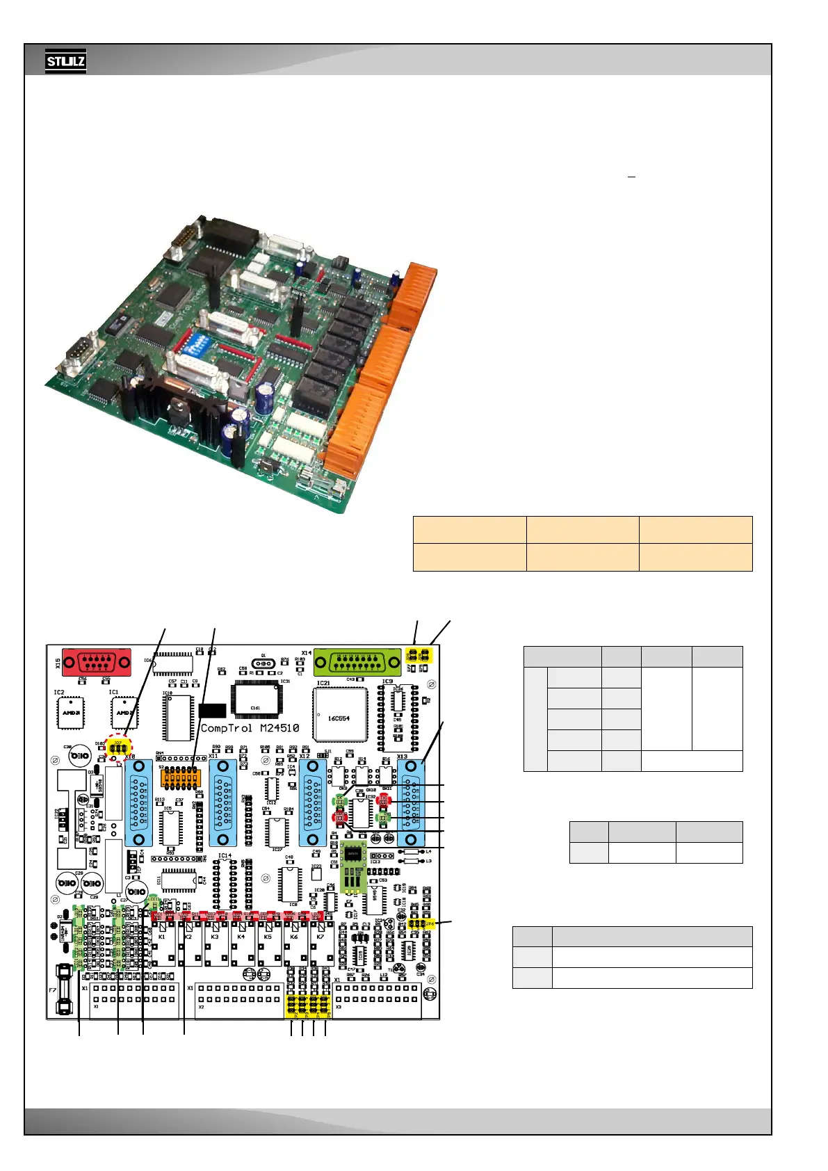
3. Hardware components
3.1 I/O controller (C7000 IOC)
Jumper settings according to the
sensor type
Jp n° Pos.1-2 Pos.2-3
Analog inputs
A-IN 1 2
4-20 mA
0-10 V
A-IN 2 3
A-IN 3 4
A-IN 4 5
A-IN 5 6 not usable*
Pin position of X1
Service port
RS232
Plugs for EBUS
exp. board
Jumper for software download
Jp n° Pos. 1-2 Pos. 2-3
7 Operation Download
EBUS activation
Jp n° Function, when set
8 EBUS port 2 deactivated
9 EBUS port 3 deactivated
Jp8 and Jp9 have to be set if there is no EBUS
expansion board. On the contrary, they have to be
removed to activate the RS485 expansion buses
on the plugged EBUS expansion board.
Green LEDs for red LEDS for
digital inp. 1-11 digital outp. 1-7
LEDs on the circuit board
The function of the digital inputs is indicated by the
green LEDs:
ON: voltage present
OFF: no voltage (Alarm, error)
The function of the digital outputs is displayed by
the red LEDs:
ON: relay energized
OFF: relay not energized
The OK LED displays the IIC bus clock. The sensors
are evaluated in this cycle.
The TX1/RX1 LEDs display the data traffic on the
I/O bus (port 1).
The Error LED lights up if an alarm has occurred.
Dipswitch
for bus adr.
4 sockets
for EDIOs/
EAIOs/
EEIO
Driver module
for the I/O bus
Technical data:
Electrical supply: 24(+15 %) V (AC)
Power consumption: 9.6 VA
Fuse: 2 A inactive
Operating temperature: 5 °C to 40 °C
Storage temperature: -30 °C to 60 °C
For further information, see page 12.
*Exception: for PT1000/100 on existing
systems