BA C7000 for EC Tower | EN | 01-2019 | 1000755
58
Bus
addr.
Dipswitch
1 2 3 4 5
0 0 0 0 0 0
1 1 0 0 0 0
2 0 1 0 0 0
3 1 1 0 0 0
4 0 0 1 0 0
5 1 0 1 0 0
6 0 1 1 0 0
7 1 1 1 0 0
8 0 0 0 1 0
9 1 0 0 1 0
10 0 1 0 1 0
11 1 1 0 1 0
12 0 0 1 1 0
13 1 0 1 1 0
14 0 1 1 1 0
15 1 1 1 1 0
16 0 0 0 0 1
17 1 0 0 0 1
18 0 1 0 0 1
19 1 1 0 0 1
IOC bus
addr.:01
IOC bus
addr.:03
IOC bus
addr.:07
IOC bus
addr.:08
IOC bus
addr.:15
AT bus
addr.:18
IOC bus
addr.:17
IOC bus
addr.:14
RS 485
56 57 58 59 56 57 58 59
LOW
HIGH
Bus
addr.
Dipswitch
1 2 3 4 5
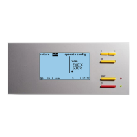
You need a shielded cable with lines twisted in pairs and a characteristic impedance of
120 Ω (recommendation Belden 9841), which you guide from unit to unit and connect at
terminals 56-59 on each I/O controller (IOC). In the example below, the bus termination
must be carried out for both units which form the end (IOC 01 and IOC 17).
The example shows a typical application with 7 IOCs and 1 C7000 Advanced (AT).
9.2.4 Adjusting the bus addresses
The bus addresses is adjusted with the dipswitches on the C7000IOC circuit board.
The table on the right shows the corresponding settings for all possible bus addresses.
Ensure that the counting begins at 0. “1” stands for dipswitch in the “ON” position. If you
set a larger address than 19 for the C7000IOC, this is reduced to 19 by the software.
An IOC is delivered with the address 1 as standard; a C7000AT has the address 0 as
standard.
For the C7000AT, adjust the bus address in the placing view.
Bus termination:
See description of the driver
module on page 12.
Terminals
on IOC
Terminals
on IOC
In short:
1. Connect units with bus line
2. Set bus termination (beginning/end)
3. Adjust Bus IDs
4. Confirm bus configuration
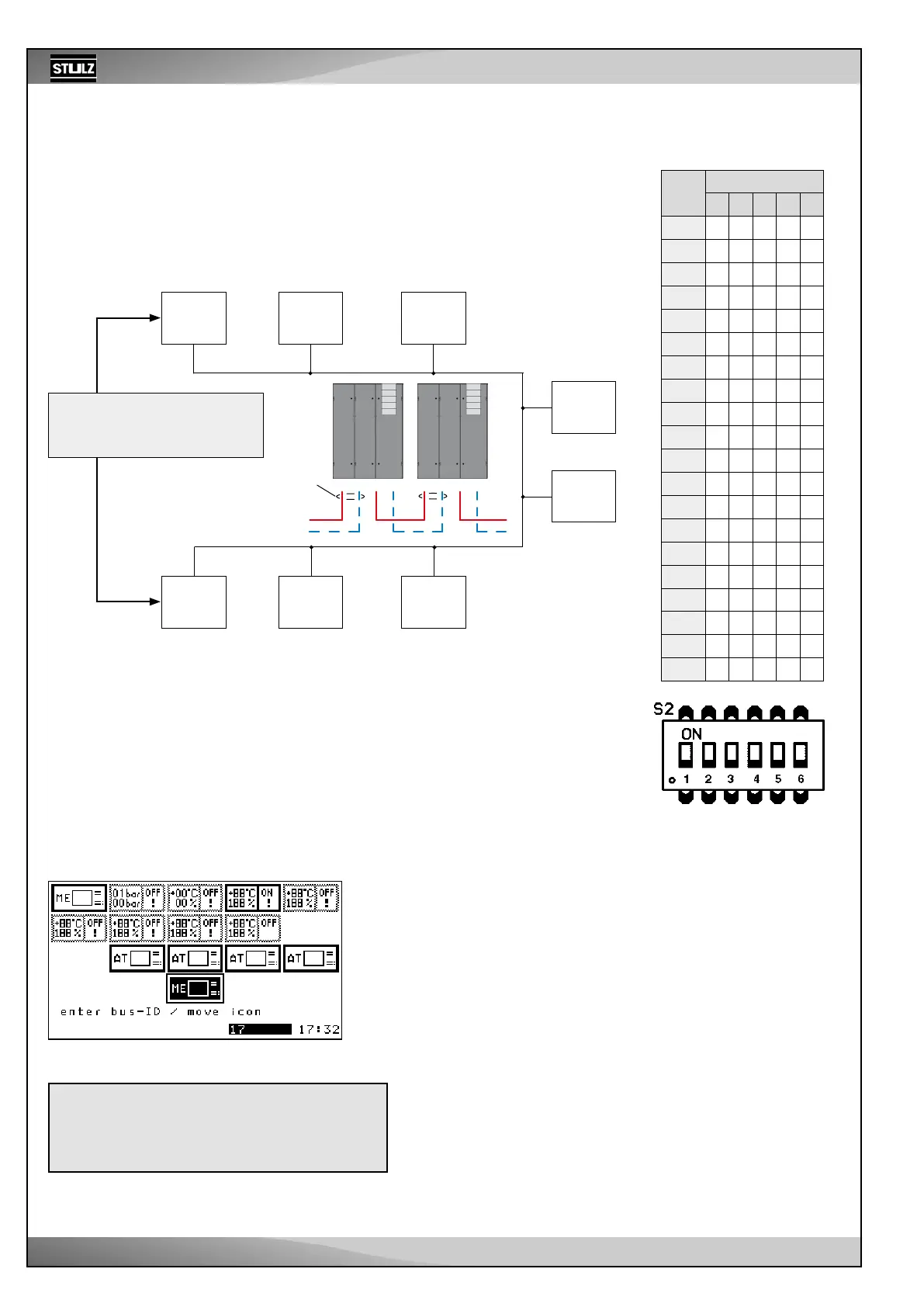
Screen
Using the selector button, you can move the C7000AT with the symbol
“ME” to a new position and thus change its bus address.
In the picture: old position address 0, new position address 17.
Press the OK button to confirm the selection.
Now, the bus configuration has to be confirmed so that no error is
displayed because there is no bus participant with address 0 anymore.
The address of the remaining bus participants is not changed by this.
9.2.3 Manual preparations
Placing view
Chapter “5. Controller start” on page 14 describes how to get
to the placing view and how to confirm the current configuration.