Installation STULZ UltraWater 3-stage reverse osmosis system SUW
© STULZ GmbH, Hamburg
-
22
-
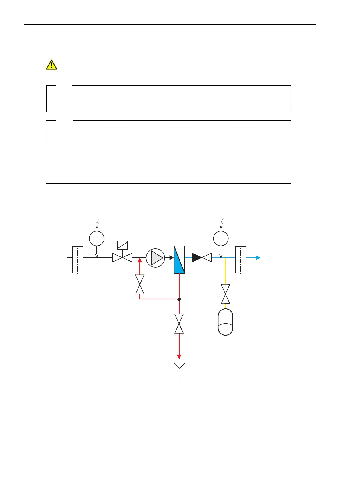
Permeate =
pure water
(approx.0...3bar)
Feed=
supply
(1...5bar)
p
RO module
Non-return
valve
Drain valve
or ball valve
with aperture
Working
pressure
valve
Pump
Prefilter
p
Afterfilter
Pressure tank
(membrane expansion tank)
I-O-Plan
RO-EXCEL-DTP-1-1.CDR
Version2
:26.07.2014
B.Ramsch
UmkehrosmoseanlagenExcel DTP(3)1:1
Maßstab:
Material:
GmbH
&
Co.
KG
AquaCare
Am Wiesenbusch
11
D-45966
Gladbeck
Germany
phone:+49-20 43-375758-0
fax: +49-2043-375758-90
email:info@a quacare.de
Intake pressure switch
Function: NO
Hysteresis:approx.0.5...1.0bar
Inlet
solenoid valve
Function: NC
Tank pressure switch
Function: NC
Hysteresis:approx.2.0-3.0bar
Tank
valve
Concentrate =
waste water
(0...0.5bar)
Note:
Connection of the pressure tank is absolutely essential for reliable operation of ultrasonic
humidiers with the reverse osmosis system!
Install a pressure reducer upstream of the system, which restricts the
intake pressure to max. 4 bar.
Note:
Note:
During installation, the reverse osmosis system must be separated from the drinking wa-
ter mains by a backow preventer.
In sensitive areas where leaks must be avoided at all costs, we recommend the use of a
leakage warning system. This will cut off the water supply in the event of a leak.
7.2. Connection diagram