Sealed System Information
Integrated
Integrated
(700-
(700-
3
3
T
T
ALL)
ALL)
Series
Series
4-4
#3758412 - Revision B - December, 2006
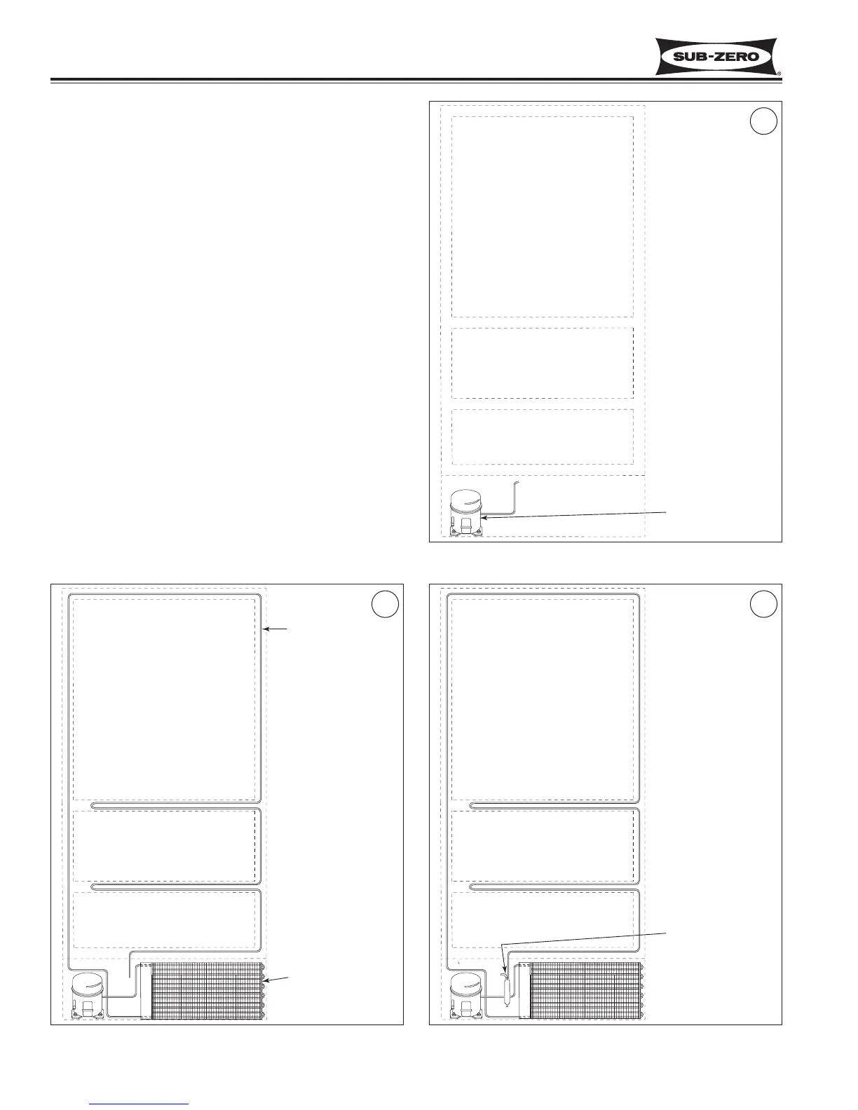
Figure 4-2. Condenser & Heater Loop
SEALED SYSTEM OPERATION
The six diagrams on these pages illustrate a basic sealed
system. The components are listed in order of refrigerant
flow, with an explanation of their fundamental role as part
of a sealed system. NOTE: These illustrations do not
represent any specific 700-2 sealed system.
Compressor (Figure 4-1)
The compressor creates a high side and low side pressure
difference in the sealed system by compressing the refrig-
erant gas, thus raising the pressure and temperature. The
compressor pushes this high-pressure/high-heat gas to the
condenser.
Condenser (Figure 4-2)
The high-pressure/high-heat gas travels through the con-
denser, where the heat is dissipated by cooler air being
drawn over the condenser tubing by the condenser fan.
This changes the gas into a high-pressure/warm liquid that
is then routed through the door gasket seat heater loop to
prevent sweating. After traveling through the heater loop,
the high-pressure/warm liquid enters the high-side filter-
drier.
Filter-Drier (Figure 4-3)
The high-pressure/warm liquid travels through the high-
side filter-drier, which removes moisture from the refriger-
ant before it enters the capillary tube.
Figure 4-3. Filter-Drier
Figure 4-1. Compressor