Section 2
DESCRIPTION
6
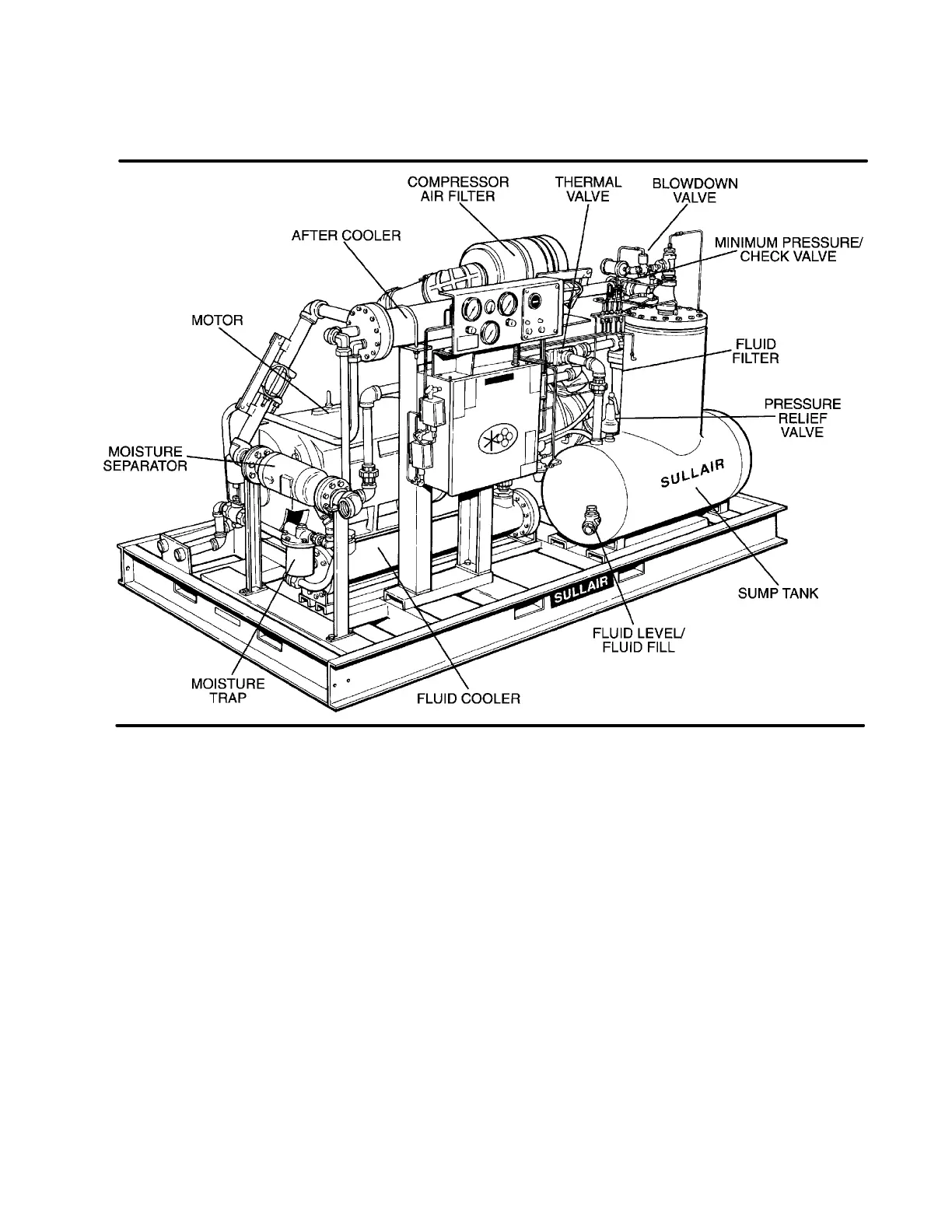
Figure 2-2 Sullair 20/12 Rotary Screw Air Compressor (Water-cooled)
As the rotors turn, air is drawn into the compressor
unit at the first stage inlet. At the outlet of the first
stage the air is compressed and discharged into the
second stagewhereit is compressedagaintoobtain
a higher pressure.
Lubricating fluid is injected into the compressor unit
at each stage whichmixes directly with the air as the
rotors turn, compressing the air. The fluid flow has
three basic functions:
1. As coolant, it controls the rise of air temperature
normally associated with the heat of compres-
sion.
2. It seals the leak paths between the rotors as well
as between the rotors and stators.
3. It acts as a lubricating film between the rotors al-
lowing the male rotors to directly drive the female
rotors (which are idlers).
After the air has been compressed in both stages of
the compressor unit, it is discharged in the form of
an air/fluid mixture. This mixture is routed through
the discharge system where the fluid is separated
from the air. At this time, the air flows to your service
line and the fluid is directed through the cooling and
lubrication system in preparation for reinjection.
2.4 COMPRESSOR COOLING AND LUBRICATION
SYSTEM, FUNCTIONAL DESCRIPTION
Refer to Figures 2-3, 2-4 and 2-5. The compressor
cooling and lubrication system is designed to pro-
vide adequate lubrication as well as maintain the
proper operating temperature of the compressor.
The system is comprised of a shell and tube or ra-
diator type heat exchanger, main line filter, extra-
fine bearing lubefilter, thermal valve, fluid stop valve
and interconnecting piping.
Fluidisusedinthesystemas acoolantandlubricant
and is housed in the receiver/sump (from this time
forward, the receiver sump will be referred to as the
sump). Fluid circulation is achieved by forcing the
fluid from the higher pressure area of the sump to
lower pressure regions at the compressor unit.
Fluid flows from the bottom of the sump to the ther-
mal valve. The thermal valve is fully open to the
compressor unit when the fluidtemperature is below
220ºF (104ºC).

 Loading...

