Section 2
DESCRIPTION
11
reaching the Sullicon Control. Should the pressure
begintorise, the pilot pressure regulator will resume
its normal function as previously described.
For a compressor with varied periods of time when
there are no air requirements, a “Dual Control” op-
tion is available. This option allows you to set the
compressor in an automatic position whereby the
compressor will shut down (time delayed) when no
compressed air requirement is present and restart
as compressed air is needed.
2.7 AIR INLET SYSTEM, FUNCTIONAL DESCRIP-
TION
Refer to Figure 2-7. The compressor inlet systems
consists of a dry-type air filter, a restriction gauge,
inlet actuator cylinder, Sullicon Control, and an air
inlet valve.
The restriction gauge, locatedon the compressor in-
strument panel, indicates when air filter mainte-
nance is required.
The butterfly-type air inlet valve directly controls the
amount of air intake to the compressor in response
to the operationof the Sullicon Control(Section2.6).
The inlet actuator cylinder holds the butterfly valve
closed during the compressor start mode.
2.8 INSTRUMENT PANEL GROUP, FUNCTIONAL
DESCRIPTION
Refer to Figure 2-8 for specific location of parts de-
scribed. The instrument panel group consists of a
line pressure gauge, air filter maintenance
gauge, sump pressure gauge, compressor dis-
charge temperature gauge and maintenance in-
dicators for the separator elements and bearing
filterall located on a heavy gauge instrument panel.
Located on the electric control panel are START,
STOP and RESET (optional) pushbuttons, power
and run indicators,anhourmeter, plus various
(optional) fault indicator lights (see Figure 2-8).
Refer to Figure 2-8 for functional locations of the fol-
lowing indicators and controls:
S Theline (terminal) pressure gauge isconnected
to the dry side of the receiver downstream from the
check valve and continually monitors the air pres-
sure.
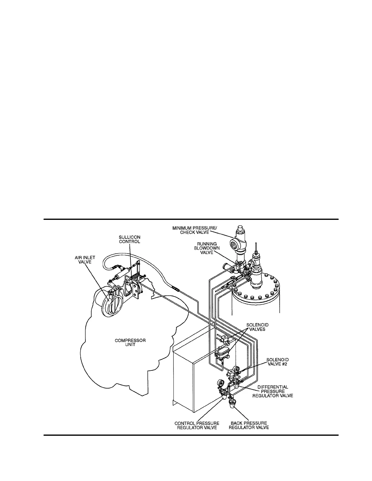
Figure 2-6 Control System

 Loading...

