Section 2
DESCRIPTION
7
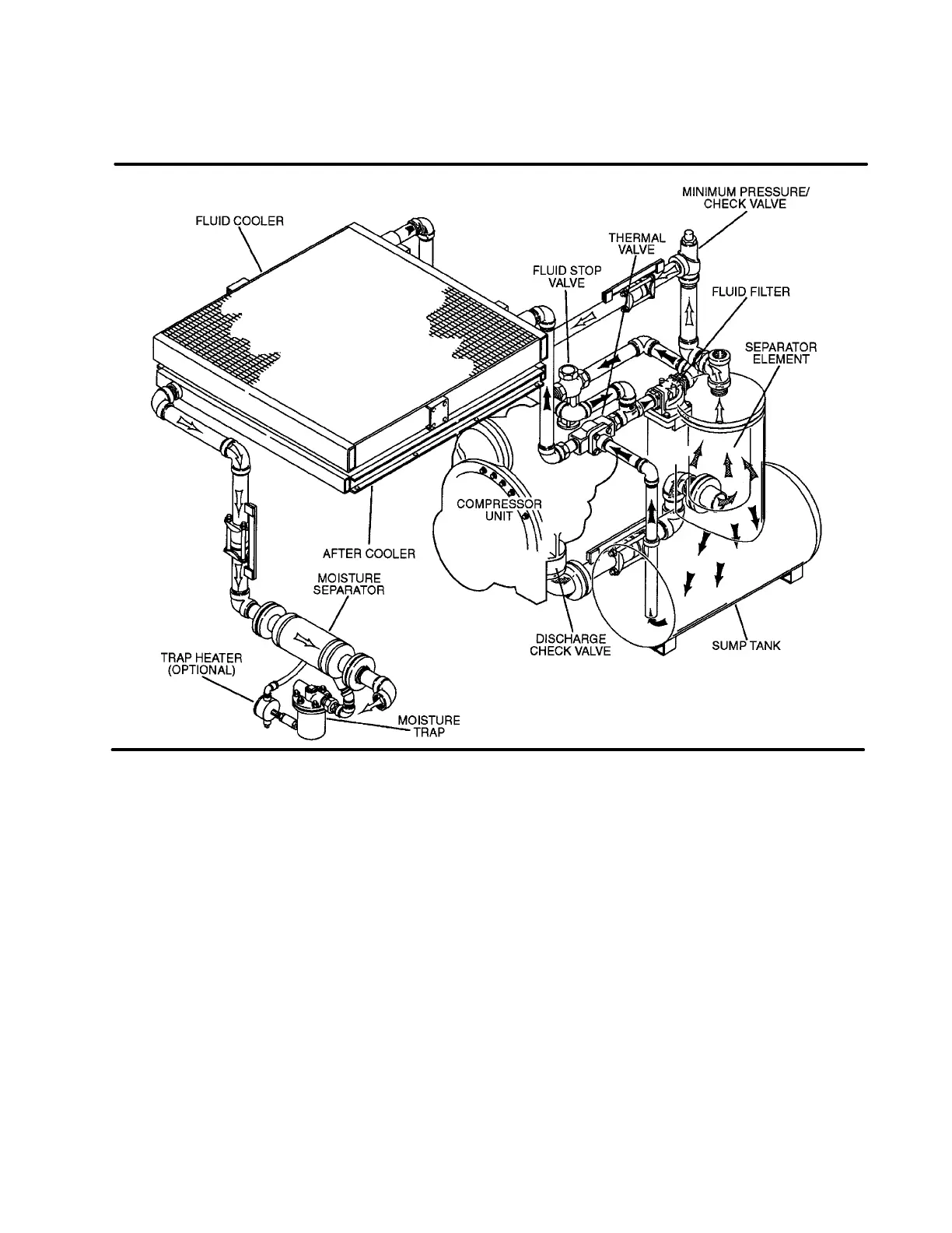
Figure 2-3 Compressor Cooling/Lube and Discharge (Air-cooled)
After the fluid passes through the thermal valve, it is
then directed through thefluidfilter. Therethefluidis
filtered in preparation for injection into the compres-
sion chambers. This filter has a cleanable element
and built-in bypass which allow some fluid to flow
even when the filter becomes plugged and requires
changing, or when the viscosity of the fluid is too
high for adequate flow. After the fluid is properly fil-
tered, it then flows to the fluid stop valve and on to
the bearing filter.
The fluid stop valve prevents the fluid from filling the
compressor unit when it is shut down. When the
compressor is in operation, the fluid stop valve is
held open by air pressure from the compressor unit
allowinga freeflowof fluid from the sump back tothe
compressor unit. On shutdown, the compressor unit
pressure is reduced, causing the fluid stop valve to
close and isolate the unit from the cooling system.
The fluid stop valve solenoid valve also opens to as-
sist in relievingthe stop valve pilot signal pressure at
shutdown.
A portion of the fluid flowing to the compressor is
routed to the anti-friction bearings which support the
rotors inside the compressor unit. Prior to entering
the compressor unit, this fluid is taken through an
extra-fine bearing filter, thus assuring properly fil-
tered fluid for bearing supply.
The bearing filter has a replaceable element and an
integral pressure bypass valve. An associated
maintenance indicator shows red when the filter
needs servicing. This indicator has a pressure set-
ting lower than that of the bypass valve. After the in-
itial 50hour filter change, the filter indicator will show
red when filter conditions require a filter change.
2.5 COMPRESSOR DISCHARGE SYSTEM, FUNC-
TIONAL DESCRIPTION
Refer to Figures 2-3, 2-4 and 2-5. The Sullair com-
pressor unit discharges the compressed air/fluid
mixture through a discharge check valve into the
combination receiver/sump. The discharge check
valve prevents air in the sump from returning to the
compression chamber after the compressor has

 Loading...

