Section 6
MAINTENANCE
24
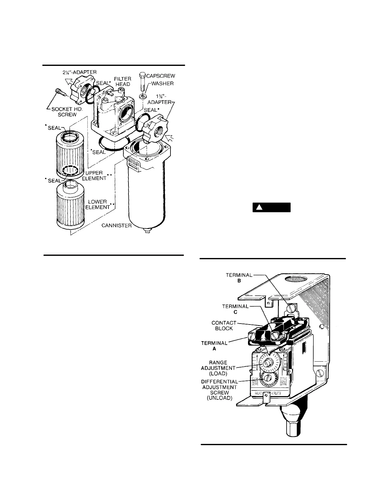
Figure 6-4 Main Fluid Filter (P/N 045111)
** Element Repair Kit P/N 001094
* Seal Repair Kit P/N 001132
CONTROL SYSTEM ADJUSTMENT
Refer to Figures 6-5 and 6-6. Prior to adjusting the
Control System, it is necessary to determine the de-
sired operating pressure range and also the maxi-
mum pressure at which your compressor is to oper-
ate. The pressure must not exceed the maximum op-
erating pressure which is stamped on the compres-
sor serial number nameplate. The following explana-
tion applies to a typical installation with a desired op-
erating range of 250 to 260 psig (17.2 to 17.9 bar).
This information will apply to a compressor with any
other operating range except for the stated pres-
sures.
With the shut-off valve closed (or slightly cracked
open) start the compressor. Observe the line pres-
sure gauge and pressure switch contacts. When the
linepressure reaches the desired pressure, the pres-
sure switch contacts should open. If the pressure
switch contacts do not open or they open prior to the
desired pressure, the pressure switch setting will re-
quire adjustment (refer to Figure 6-5).
FOR PRESSURE RANGE ADJUSTMENT:
1. Remove cover to pressure switch.
2. Turn the range adjusting screw to the high pres-
sure (unload) setting. Turning the screw counter-
clockwise lowers both the high and low pressure
equally.
FORDIFFERENTIAL PRESSURE ADJUSTMENT:
Differential is the difference between the high and
low pressure settings (10 psig [0.7 bar]) typical.
Turn the differential adjusting screw to the lower (re-
set) setting. Turning the screw counterclockwise
widens the differential by lowering the reset (lower)
setting only.
When the pressure switch adjustment is complete,
the pressure regulator should be adjusted for the
pressure at which modulation of air delivery should
begin. In this case, that pressure will be 250 psig
(17.2 bar). The regulator is adjusted by looseningthe
jam nut on the end of the cone shaped cover of the
pilot pressure regulator (refer to Figure 6-7for the lo-
cation). When the jam nut is loosened, turn the ad-
justing screw clockwise to increase or counterclock-
wise to decrease the setting.
Once the pressure rises above 260 psig (17.9 bar),
the solenoid pilot valve opens allowing pressure to
flow into the Sullicon Control. At this time theSullicon
Control should be fully stroked.
DANGER
!
DO NOT touch theelectrical contactsof the pressure
switch with any metallic object. Severe electrical
shocks may occur. Cycle the Control System several
times and recheck all the pressure settings.
Figure 6-5 Pressure Switch (P/N 245753)

 Loading...

