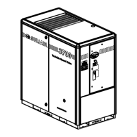
Key Description Part Number Note Quantity
A1 Tank pressure — blue color
A2 Regulator pressure – yellow color
A3 Unload pressure – red color
A4 Water drain – clear color
B1 P1 – wet sump pressure
B2 P2 – line pressure
B3 SOL 1 – load/unload solenoid valve
B4 SOL 4 – MEC/sequencing/full load solenoid valve
B5 SOL 5 – electric drain/SCD drain solenoid valve
B6 SOL 6 – water solenoid valve
B7 T1 – wet discharge temperature
B8 Water solenoid valve option
B9 Water regulating valve option
B10 Sequencing solenoid option
B11 SCD drain option
C1 ½" hose
C2 Control/moisture drain lines are ¼" tubing except as noted
C3 1 ½" – 11 ½" npt air outlet
C4 ¼"-18 npt moisture drain connection
C5 Sections between lettered points are to be replaced with corresponding option pictured below
C6 Optional head trace is applied only to control and moisture drain lines, and used only with stainless steel tubing
C7 Water inlet ¾"-14 npt
C8 Water outlet ¾"-14 npt
D1 Customer furnished line
D2 Water line
D3 Control line
D4 Fluid line
D5 Air/fluid line
D6 Temperature control probe
D7 Air line
SPECIFICATIONS
®SULLAIR®
3000-4500 Operator’s Manual and Parts List
33

 Loading...