Section 2
DESCRIPTION
6
Figure 2-2 Sullair Rotary Screw Air Compressor- Water-cooled Model
change of fluid is required, use only Sullair 24KT
fluid.
WARNING
!
Mixing of other lubricants within the compressor
unit will void all warranties!
Sullair recommends that a 24KT sample be taken at
the first filter change and sent to the factory for anal-
ysis. This is a free service. The sample kit with in-
structions and self--addressed container is to be
supplied by your Sullair dealer at start--up. The user
will receive an analysis report with recommenda-
tions.
Fluid is injected into the compressor unit in large
quantities and mixes directly with the air as the ro-
tors turn, compressing the air. The fluid flow has
three basic functions:
1. As coolant, it controls the rise of air temperature
normally associated with the heat of compres-
sion.
2. Seals the leakage paths between the rotors and
the stator and also between the rotors them-
selves.
3. Acts as a lubricating film between the rotors al-
lowing one rotor to directly drive the other , which
is an idler.
After the air/fluid mixture is discharged from the
compressor unit, the fluid is separated from the air.
At this time, the air flows through an aftercooler and
separator then to your service line while the fluid is
being cooled in preparation for reinjection.
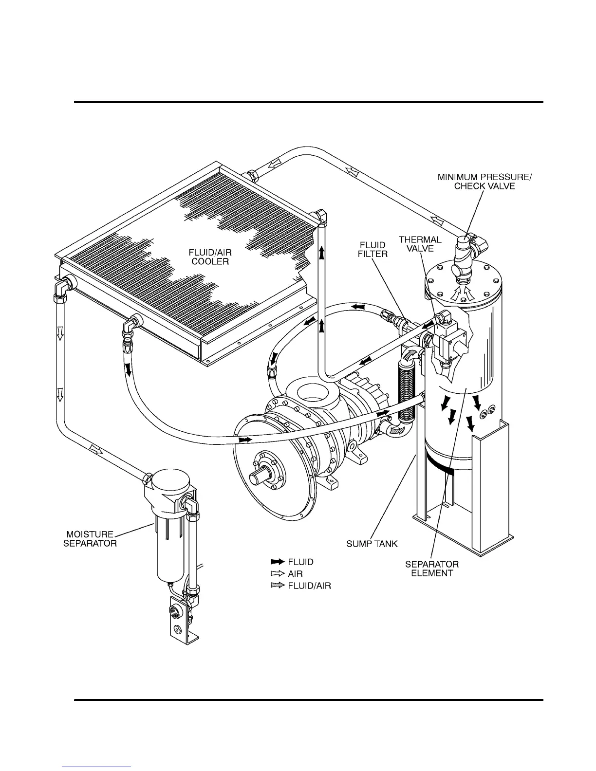
2.4 COMPRESSOR COOLING AND LUBRICATION
SYSTEM, FUNCTIONAL DESCRIPTION
Refer t o F igur es 2 -- 3A and 2 -- 3B. T he C ooling and
Lubrication System (air--cooled version) consists of
a
fan
,
double shaft drive motor
,
radiator--type af-
tercooler
and
fluid cooler
,
full flow fluid filter
,
thermal valve
, and
interconnecting piping
and
tubing
. For water--cooled models, two
shell and
tube heat exchangers
and a
water--flow regulat -
ing valve
are substituted for the radiator--type cool-
er listed above.
The pressure in the receiver/sump causes fluid flow
by forcing the fluidfrom the highpressure area ofthe
sump to an area of lower pressure in the compres-
sor unit.
 Loading...