Section 7
MAINTENANCE
44
sure setting. Turning the screw counterclockwise
lowers both the high and low pressure equally.
FOR DIFFERENTIAL ADJUSTMENT:
Differential is the difference between the high and
low pressure settings 10 psi (0.7 bar) typical.
Turn the differential adjusting screw to the lower
(reset) setting. Turning the screw counterclockwise
widens the differential by lowering the reset (lower)
setting only.
The differential pressure regulators are adjusted by
loosening the jam nut on the end of the cone
shaped cover of the pressure regulator. When the
jam nut is loose, turn the adjusting screw clockwise
to increase or counterclockwise to decrease the
setting.
Above 100 psi (6.9 bar), the regulator should allow
pressure to flow into the control chamber of the
Sullicon Control. The Sullicon Control lever should
start to move at this time. Cycle the control system
several times and recheck all pressure settings.
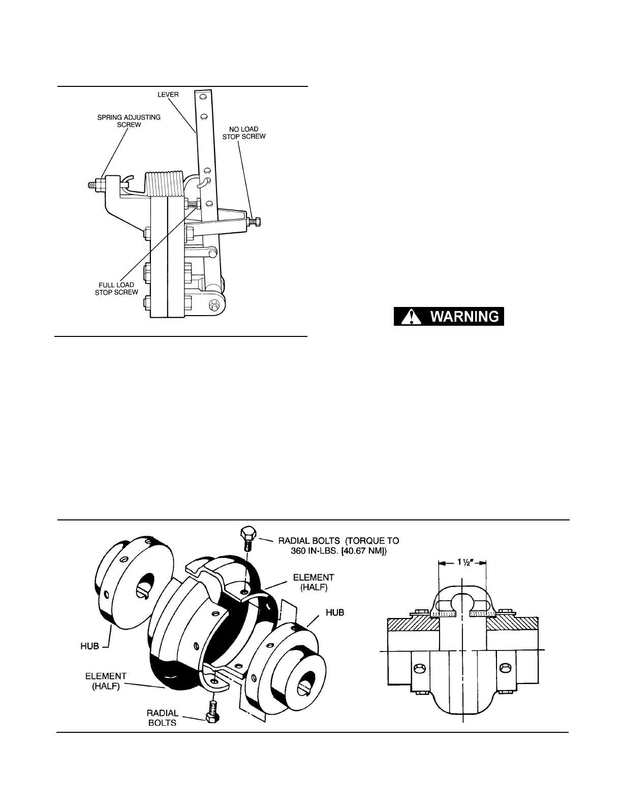
SULLICON ACTUATOR MAINTENANCE
Refer to Figure 7-5. The Sullicon actuator was ad-
justed at the factory and should require only peri-
odic lubrication of its links and pivot points to keep
operating properly. In general, if the pressure signal
(P2) is present and proper lubrication link lubrica-
tion is evident, sluggish valve operation or exces-
sive leakage indicates a damaged diaphragm. A re-
placement diaphragm is available in kit no. 250020-
353, and may be installed as follows:
Relieve package pressure before making re-
pairs.
1. Remove adjacent air signal tubework.
2. Loosen/remove cap screw fastening the valve
arm link to the Sullicon control lever and let link
hang aside.
3. Loosen/remove the two (2) capscrew/nut assem-
blies securing Sullicon to its mounting bracket
and pull Sullicon away.
4. Loosen/remove remaining capscrew/nut assem-
blies holding Sullicon body, diaphragm and cover
together. Note that control stop bracket also
comes off; without disturbing the stop screw/nut
assembly, put it aside.
Figure 7-6 Drive Coupling- 150HP/ 112KW
Figure 7-5 Sullicon Control (P/N 011682-003)
*Repair Kit P/N 250020-353
 Loading...

