Section 7
MAINTENANCE
46
and slide the motor sideways to correct the hori-
zontal offset.
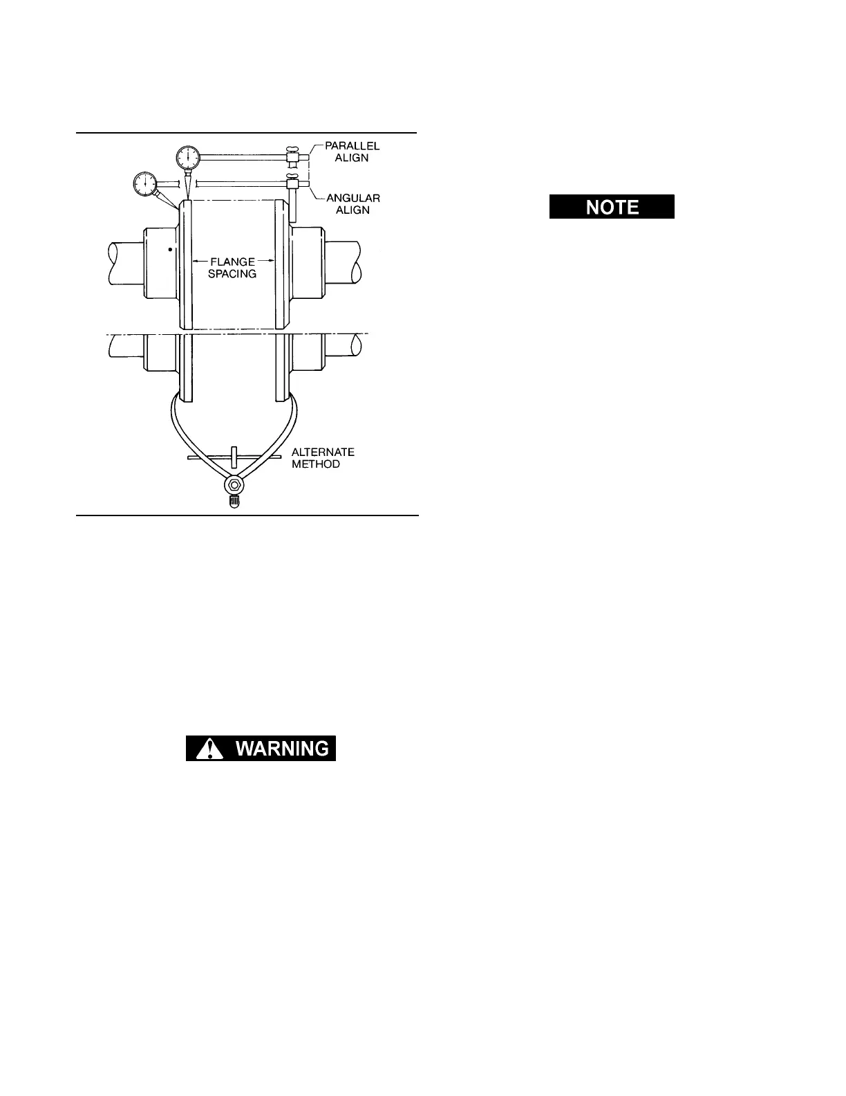
STEP 3 COUPLING GAP AND ANGULAR ALIGN-
MENT - Position the hubs to establish the proper
gap and angular alignment as indicated in Table 1.
To determine the angular misalignment in inches,
measure the maximum space between the hub
flanges and the minimum space 180º away, and
then subtract. To adjust the horizontal angular mis-
alignment, loosen the motor mounting bolts and ad-
just the motor position until the angular alignment is
within tolerance.
DO NOT upset the offset alignment or hub gap
when adjusting motor position.
When within the limits specified in Table 1, tighten
the motor mounting bolts and recheck the offset
and angular alignment. If the vertical angular align-
ment is not within .010 tolerance, shim the front or
rear of the motor separately to correct. Recheck the
vertical offset.
STEP 4 INSTALL THE FLEXIBLE ELEMENT-
Position the motor and compressor key ways 180º
apart. Insert the flexible element between the two
hubs. The element should be compressed prior to
insertion. The element can be compressed by tight-
ening a suitable sized radiator hose clamp around
the outer edge of the element as shown in Figure 7-
7. Slide the ferry head capscrews with lockwashers
through the holes in the hubs and element. Tighten
the bolts to 200 ft.-lbs. (272 Nm).
Bolts are 3/4-10 x 4” NAS 144 black oxide coat-
ed. DO NOT substitute with any other bolts.
After tightening the hex bolts, tighten the shaft
setscrews and remove the hose clamp from the
flexible element. At this time, the coupling is ready
for operation.
DRIVE COUPLING DISASSEMBLY AND RE-
MOVAL- 200HP/ 149KW
Disassembly and removal of the drive coupling is
done in the following manner:
1. Place a suitable sized radiator hose clamp over
the flexible element as show in Figure 7-6 and tight-
en a sufficient amount to compress the rubber.
2. Remove the ferry head bolts from the hubs and
element.
3. Rotate the element until the studs clear the hubs.
4. Remove the element from the hubs with the hose
clamp still in place.
5. Loosen the shaft setscrews and remove the
hubs.
7.6 TROUBLESHOOTING INTRODUCTION
The information contained in the Troubleshooting
chart has been compiled from field report data and
factory experience. It contains symptoms and usual
causes for the described problems. However DO
NOT assume that these are the only problems that
may occur. All available data concerning the trouble
should be systematically analyzed before undertak-
ing any repairs or component replacement proce-
dures.
A detailed visual inspection is worth performing for
almost all problems and may avoid unnecessary
additional damage to the compressor. Always re-
member to:
a. Check for loose wiring.
b. Check for damaged piping.
c. Check for parts damaged by heat or an electrical
short circuit, usually apparent by discoloration or a
burnt odor.
Should your problem persist after making the rec-
ommended check, consult your nearest Sullair
Distributor or the Sullair Corporation factory Service
Department.
Figure 7-9 Parallel/ Angular Offset Alignment
(200HP/ 149KW)
 Loading...

