Section 7
MAINTENANCE
43
1. Relieve all pressure from the sump tank and
package pipework.
2. Disconnect all pipework connected to the sump
cover.
3. Loosen and remove the twelve (12) hex head
capscrews (3/4” x 2 1/2”) from the cover plate.
4. Lift the cover plate from the sump.
5. Remove the two (2) nested separator elements.
6. Scrape the old gasket material from the cover
and sump flange - avoid dropping any scraps into
the sump.
7. Inspect the sump vessel for rust, dirt, etc.
8. DO NOT remove grounding staples from the gas-
kets. DO NOT use any type of gasket eliminator.
Reinsert the separator element, with gasket at-
tached, into the sump, taking care not to dent the
former against the tank opening.
CONTROL SYSTEM ADJUSTMENT
Refer to Figures 7-4 and 7-5. Prior to adjusting the
control system, it is necessary to determine the de-
sired operating pressure range and also the maxi-
mum pressure at which your compressor is to op-
erate. The pressure must not exceed the maximum
operating pressure which is stamped on the com-
pressor serial number nameplate. The following ex-
planation applies to a typical installation with a de-
sired operating range of 100 to 110 psi (6.9 to 7.6
bar). This information will apply to a compressor
with any other operating range excepting the stated
pressures.
Remove the cover of the pressure switch. With the
shut-off valve closed (or slightly cracked open) start
the compressor. Observe the line pressure gauge
and pressure switch contacts. When the line pres-
sure reaches the desired unload (maximum) pres-
sure, the pressure switch contacts should open. If
the pressure switch contacts do not open or they
open prior to the desired pressure, the pressure
switch setting will require adjustment (refer to
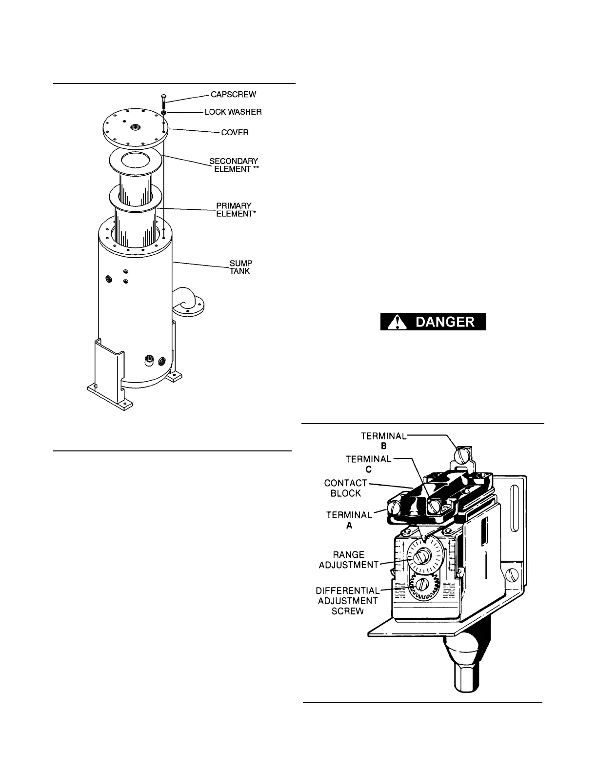
Figure 7-4).
DO NOT touch the electrical contacts, terminal
or leads with any metallic object. Severe electri-
cal shock may occur.
FOR PRESSURE RANGE ADJUSTMENT:
1. Remove cover to pressure switch.
2. Turn the range adjusting screw to the high pres-
Figure 7-4 Pressure Switch (P/N 042570)
Figure 7-3 Separator Element Replacement
*Replacement Element (primary) P/N 250034-085
** Replacement Element (secondary)
P/N 02250047-808
 Loading...

