Section 5
19
PRINCIPLE OF OPERATION
PRINCIPLE OF OPERATION
The refrigerant circuit can be divided in 3 parts:
1. Low pressure section with an evaporator
(heat exchanger)
2. High pressure section including: Condenser,
liquid receiver, (if installed) and the filter
dryer.
3. Control circuit including: Compressor, meter-
ing device, hot gas by-pass valve (if
installed), fan pressure switch, safety high/
low pressure switch. Water cooled dryers are
equipped with a water flow control valve.
5.1 REFRIGERATION HEAT
EXCHANGER
1. There are two (2) basic sections, commonly
referred to as the high and low-pressure sec-
tions, in a refrigeration circuit. The high side
begins at the refrigerant compressor dis-
charge port and ends at the expansion
devise. The circuit leaving the expansion
devise through the air to refrigerant heat
exchanger and up to the compressor suction
port is known as the low pressure circuit. The
compressor takes in low pressure refrigerant
gas and compresses it to a high pressure
and high temperature gas. The high temper-
ature gas passes into the refrigerant con-
denser where it is cooled and liquefied. The
refrigerant then passes through the filter
dryer where moisture and any foreign parti-
cles are removed. The refrigerant then
passes through an expansion device where
the liquid refrigerant is throttled and a tem-
perature drop will occur as part of the liquid
turns into gas. The cold refrigerant gas and
liquid then enters the refrigerant-to-glycol
heat exchanger where it absorbs the heat
from the glycol as it evaporates. The low-
pressure refrigerant gas returns to the com-
pressor for repetition of the process.
2. Glycol Side: The thermal mass is food safe
and environmentally friendly polypropylene
glycol solution. It is pumped continuously
through the heat exchangers to eliminate
any dew point fluctuations commonly found
in other cycling dryers. The glycol is stored in
a stainless steel insulated tank with welded
connections. The glycol flows through the
pump to the Air-to-Glycol chamber located in
what is commonly termed as the heat
exchanger where it cools the compressed air
by counter flow. From there, it travels to the
evaporator where heat is extracted out by
the refrigerant. The heat saturated glycol
then returns to the storage tank. A tempera-
ture probe in the tank monitors the tempera-
ture and turns off the compressor when the
glycol reaches its set point. A float switch
inside the glycol tank shuts off the unit if the
glycol level drops below the minimum height.
3. Refrigerant controls: High-low refrigerant
cut-out switch senses high and low refriger-
ant pressure at refrigerant compressor inlet
and outlet ports shutting the compressor
down in the event of high refrigerant dis-
charge pressures or low refrigerant suction
pressure.
4. Liquid line filter dryer: Filters refrigerant of
moisture and any foreign particles. Must be
replaced if the refrigerant system has been
opened causing exposure to atmospheric
pressures.
5. Expansion device: Meters refrigerant flow in
the evaporator.
6. Electronic drain valve: An electronic drain
valve on the separator is designed to open
and close automatically to drain away con-
densate.
7. Crank case heater: A safety device which
prevents refrigerant migration back to the
compressor during shutdown.
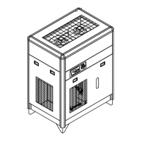
8. Air cooled models Cooling air flows from the
front to the back of the dryer. Air must be
drawn from a clean source in order to reduce
 Loading...