INSTALLATION, START-UP & MAINTENANCE MANUAL
MODEL NO.: SD-820 / SD-1710
REV 1 – AUGUST 03,.2001
Page 33
SECTION 6
6.2 SERVICE BULLETIN
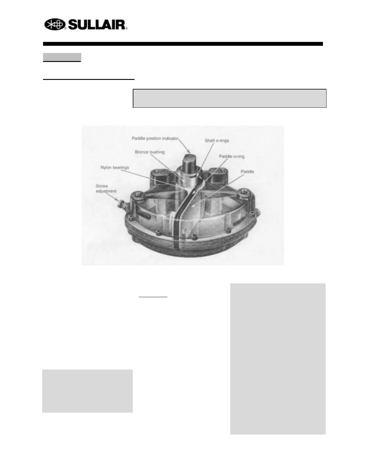
Vane Type Actuator
Installation, Operation & Service Instructions
Vane type actuators are compact 90°
rotary pneumatic devices to operate
quarter-turn valves.
They are designed for pressures
(supply and/or exhaust) up to 120
PSIG maximum.
WARNING !
Explosion. DO NOT EXCEED
PRESSURE RATINGS : excessive
pressure may rupture the actuator and
cause personal injury and/or property
damage.
Installation
1. Vane actuators are shipped from
the factory with an indicator line
stamped on the shaft ends which
shows the position of the vane
paddle. This indicator should be
used in determining the mounting
orientation of the actuator on the
valve.
2. Before mounting, the actuator and
the valve must be placed in the
same position (fully counter-
clockwise or fully clockwise).
Check the valve and actuator
mounting surfaces, bracket, stem
adapter and valve stem for proper
orientation and fit.
WARNING !
VALVE & ACTUATOR DAMAGE.
Once installed, leave at least 1-16 inch
axial clearance between the end of the
actuator shaft and the drive coupling
to prevent valve and actuator damage.
3. Use all mounting holes provided
on the actuator and assure a full
bolt diameter of thread
engagement into the actuator
housing as a minimum.
4. Tighten all bolts and nuts
uniformly, taking care to center
the actuator on the valve stem.
 Loading...