Section 7
MAINTENANCE
38
SEPARATOR ELEMENTS REPLACEMENT
Ref er to Figur e 7 --- 3 . The s epar ator el ements must
be changed when “Separator Maintenance Re-
quired” message is displayed, or once a year
whichever occurs first. Follow the procedure ex-
plained below for separator element replacement.
PROCEDURE FOR 200---300HP/150---225K W
ELEMENT REPLACEMENT
1. Relieve all pressure from the separator and all
compressor lines prior to disconnecting any
pipes, tubing, etc.
2. Disconnect all piping connected to the separator
cover to allow removal (return lines, service
lines, etc.).
3. Loosen and remove the twelve (12) #@4”x3”hex
head capscrews from the cover plate.
4. Lift the cover plate from the separator.
5. Remove the primary and secondary separator
elements.
6. Scrape the old gasket material from the cover
and flange on the sump being careful not to let
the scraps fall in the sump.
7. Inspect the separator tank for rust, dirt, etc.
8. Reinsert the separator elements with gaskets at-
tached into the sump taking care not to dent
them against the tank opening. DO NOT re-
move grounding staples. Check between sepa-
rator element flange and tank for continuity after
torquing bolts. DO NOT use anti---seize com-
pound on gaskets.
9. Clean the underside of the separator tank cover
and remove any rust.
10. Replace the cover plate, washers and
capscrews. Torque to 200 ft.---lbs. (271 Nm).
11. Reconnect all piping making sure return line
tubes extend to the bottom or !@4” (6mm) above
the bottom of the separator element. This will as-
sure proper fluid return flow to the compressor.
12. Check the return line strainer before restarting
the compressor (order replacement kit P/N
241772 if required).
PROCEDURE FOR 400---600HP/300---450K W
ELEMENT REPLACEMENT
1. Relieve all pressure from the separator and all
compressor lines prior to disconnecting any
pipes, tubing, etc.
2. Loosen and remove the twelve (12) #@4”x3”hex
head capscrews from the cover plate.
3. Lift the cover plate from the separator.
4. Loosen and remove the twelve (12) nuts and
washers from the retaining ring studs and re-
move the retaining ring.
5. Remove the gasket, and primary and secondary
separator elements.
6. Scrape the old gasket material from the retaining
ring and flange on the sump being careful not to
let the scraps fall in the sump.
7. Inspect the separator tank for rust, dirt, etc.
8. Reinsert the replacement separator elements
into the sump taking care not to dent them
against the tank opening. Reinsert retaining
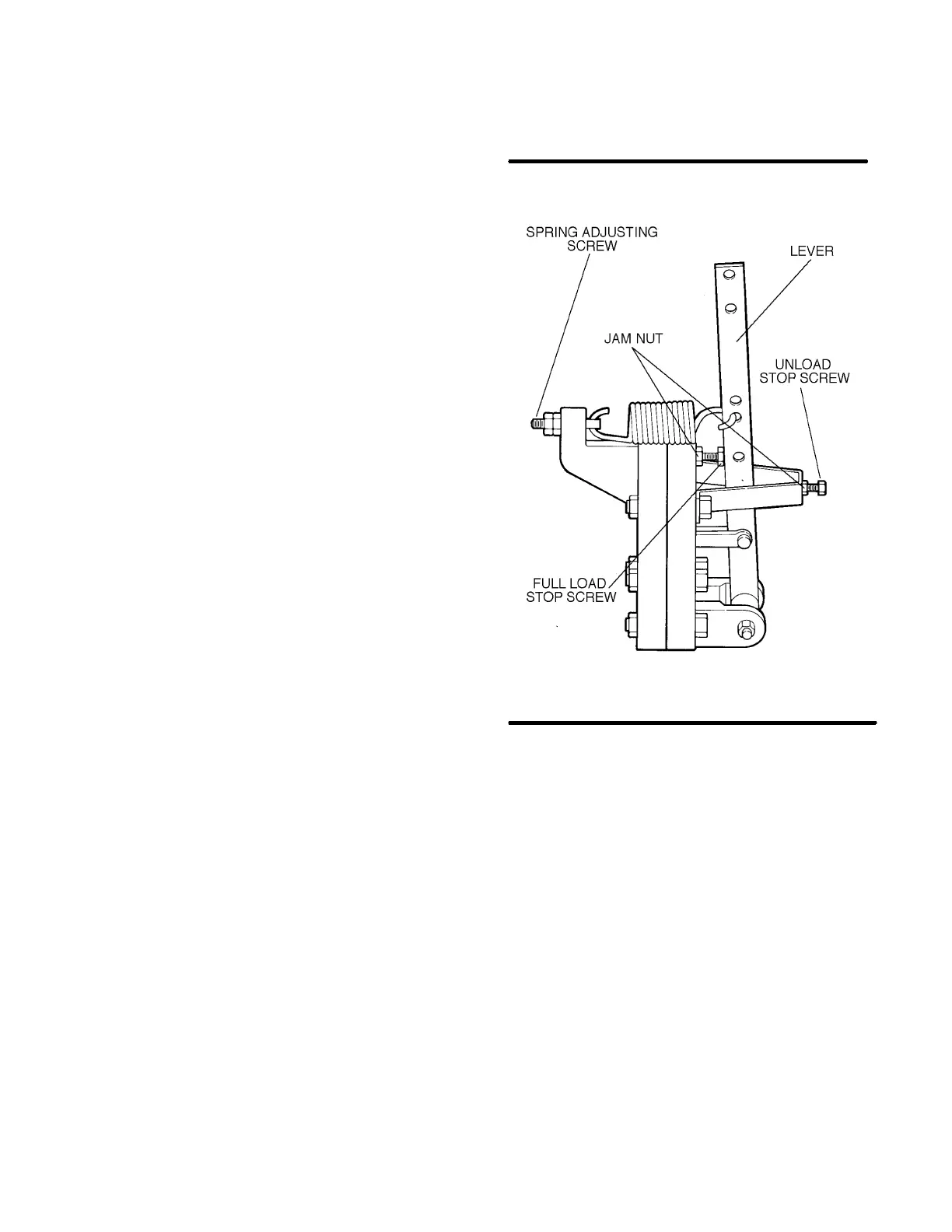
Figure 7---4 Sullicon Control (P/N 011682 ---003)
* Repair Kit P/N 250020---353
ring, washers and nuts and resecure. Torque to
30 ft.---lbs. (41 Nm). Check between separator
element flange and tank for continuity after
torquing bolts. DO NOT use anti---seize com-
pound on gaskets.
9. Clean the underside of the separator tank cover
and remove any rust.
10. Replace the cover plate, washers and
capscrews. Torque to 200 ft.---lbs. (271 Nm).
11. Reconnect all piping making sure return line
tubes extend to the bottom or !@4” (6mm) above
the bottom of the separator element. This will as-
sure proper fluid return flow to the compressor.
12. Check the return line strainer before restarting
the compressor (order replacement kit P/N
241772 if required).
CONTROL SYSTEM ADJUSTMENT
Refer to Figure 7 --- 4. Before starting the c ompres -
sor, but with power applied, press the PROG pad
on the Supervisor panel three times to enter the
PROGRAMMING mode. Continue pressing the
PROG pad until “MAX PRESS P2A” is displayed.
Use the cursor (UP arrow) pad to set the desired
 Loading...


