SECTION 6 TS32 USER MANUAL
73
SHAFT COUPLING MAINTENANCE
The compressor unit and motor are rigidly connected
through the mounting adapter housing. This
arrangement makes coupling alignment
unnecessary. The coupling is a jaw type in shear. If
the elastomeric (rubber) element requires
replacement due to wear or damage, order a
replacement element and perform the following
steps:
1. Remove the coupling guard.
2. Loosen the retaining screw located on the
outer sleeve. Slide the sleeve to one side,
exposing the coupling element.
3. Unwrap the coupling element from the
coupling jaws.
4. Position the motor and compressor keyways
180 degrees apart
5. Install the new element by wrapping it
around the jaws, engaging the cogs on the
element into the jaws.
6. Reinstall the outer sleeve and secure by
tightening the two screws to 45 in·lbs (5 Nm).
7. Reinstall the coupling guard.
6.7 DRIVE COUPLING
INSTALLATION AND
ALIGNMENT
Refer to Figure 6-7 and Figure 6-8.
For installation and alignment of the drive coupling,
follow the steps explained below.
STEP 1 MOUNT HUBS
Mount the motor hub and the compressor hub onto
respective shaft. Position the hubs to establish the
correct gap specified in Table 6-1. Secure each hub
with a setscrew.
STEP 2 OFFSET ALIGNMENT
Clean any oil, grease, dirt or paint from coupling
faces and the other surfaces of the drive flanges.
Rotate shafts so that a straight edge will rest
squarely (or within the 0.010 inch maximum limit
shown in Table 6-1) on both flanges and at a point
90° away. The vertical offset alignment is adjusted by
the addition or removal of motor mounting shims.
Loosen the motor mounting bolts and slide the motor
sideways to correct the horizontal offset.
STEP 3 COUPLING GAP AND ANGULAR
ALIGNMENT
Position the hubs to establish the proper gap and
angular alignment as indicated in Table 6-1. To
determine the angular misalignment in inches,
measure the maximum space between the hub
flanges and the minimum space 180° away, and then
subtract. To adjust the horizontal angular
misalignment, loosen the motor mounting bolts and
adjust the motor position until the angular alignment
is within tolerance.When within the limits specified in
WARNING
Disconnect all power at source, before
attempting maintenance or adjustments.
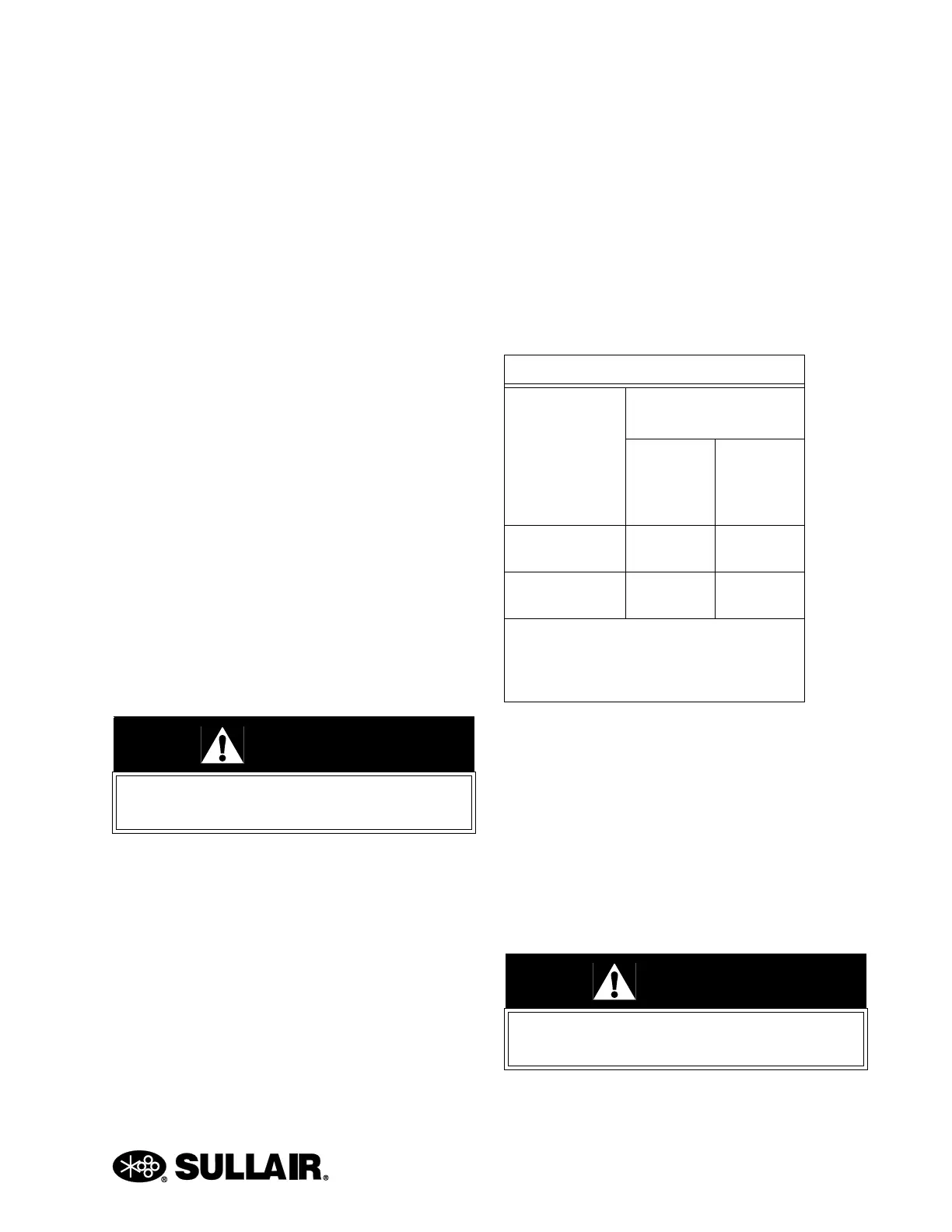
Table 6-1: INSTALLATION DATA
Coupling Gap
inches/mm
Max. Operating
Misalignment
Parallel
Offset
inches/
mm
Angular
inches/
mm (I)
.188
+/- .020 in.
.010 in. .010 in.
4.77
+/- .50 mm
.25 mm .25 mm
(I) Angular misalignment in inches equals
maximum A minus minimum B as shown in
Figure 6-7. DO NOT exceed values in Table
above.
WARNING
Disconnect all power at source, before
attempting maintenance or adjustments.

 Loading...


