24
(3) Quantity of Grease
Table 32 shows the quantity of grease required when grease needs to be changed. Approximately 1/3~1/2 of the
volume for the 1st stage reduction portion is appropriate when grease needs to be replenished.
Single reduction
Double reduction
Frame size
606
607 608 609 610 611
Reduction
portion
Qty of grease (g)
25 25 65 90 140
Slow speed shaft
bearing portion
Qty of grease (g)
35 35 70 100 100
200
90
612
330
120
Frame size
606 DA 607 DA 609 DA 610 DA 612 DA 612 DB 613 DA 613 DB 613 DC 614 DA 614 DB 614 DC 616 DA 616 DB 616 DC 617 DA 617 DB 617 DC
1st stage
(I/P side)
reduction
portion
Qty of grease (g)
25 90 25
2nd stage
(O/P side)
reduction
portion
Qty of grease (g)
25 90 140 330 450 750 1000
500
2nd stage (O/P
side) slow speed
shaft bearing
portion
Qty of grease (g)
35
618 DA 618 DB 619 DA 619 DB
6205DA 6205DB 6215DA 6215DB 6225DA 6225DB 6235DA 6235DB 6245DA 6245DB 6255DA 6255DB 6265DA
1100
140 450 330 450 330 450 750 450 1000 750 1100 750 1100 1000 1500 1500
1500 1500 2000 2500 4000 4500 6000 8000
600 700 700 800 900 1000 1100 1200 1300
35 100 100 120 300
Frame size
1st stage
(I/P side)
reduction
portion
Qty of grease (g)
2nd stage
(O/P side)
reduction
portion
Qty of grease (g)
2nd stage (O/P
side) slow speed
shaft bearing
portion
Qty of grease (g)
90 140 25 90 140 90 140 330 90 140 330
• : Long-life grease series
• Space/volume ratio : Ratio of grease to the volume of space
• 0, 5, or H is inserted in .
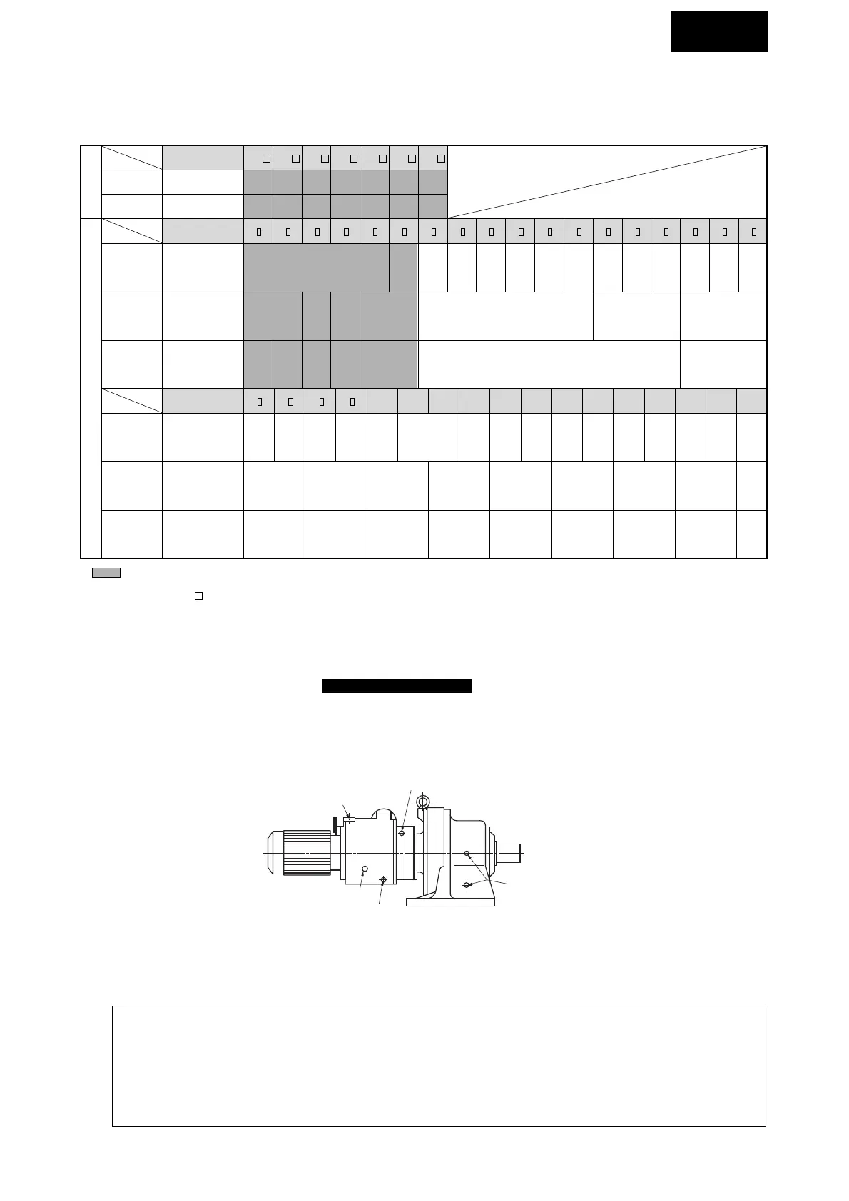
Table 32 Qty of Grease
COMMON
(4) Supply and Discharge of Grease
Procedure for supplying grease for grease-lubricated models (excl. Long-life grease series)
1 Remove the grease discharge plug from the outside cover.
2 Supply grease with a grease gun through the grease nipple in the inside cover section or motor connection cover.
3 Replace the grease discharge plug.
Fig. 19 Location of Grease Discharge Port
• Fill with grease during operation to ensure proper, uniform circulation.
• Fill with grease slowly.
• Grease supply exceeding the quantity shown in Table 32 will cause temperature rise from agitation heat or leakage
of grease into BEIER part.
• Apply grease liberally to bearings (especially to eccentric bearings), pins, rollers, and toothed section of the cyclo
discs. (Refer to 13–3. Drawing on page 36.)

 Loading...


