10
FB BRAKE ASSEMBLY – INSPECTION,
ADJUSTMENT & MAINTENANCE
2. Construction and Operating Principles
a. Construction
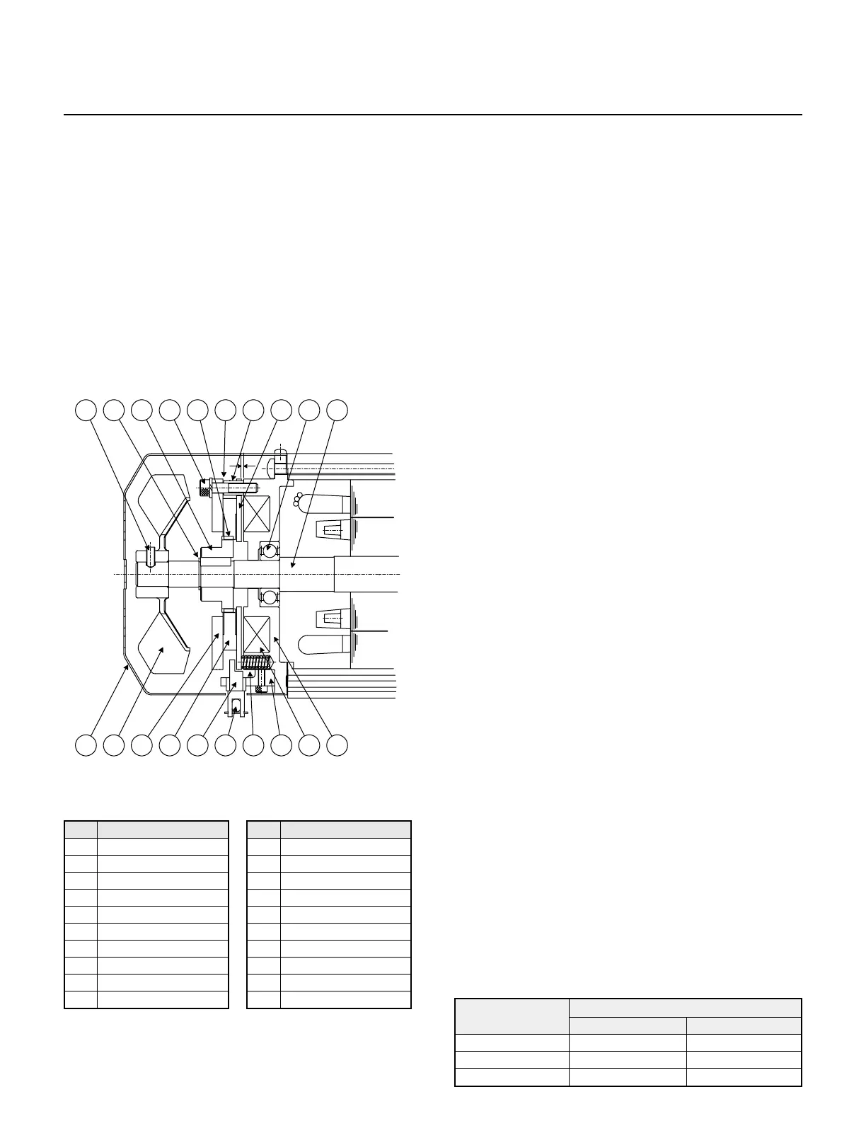
Fig. 17 illustrates the construction of the brake. The
restraining bolt (7) fastens the brake shoe (15), gap
adjusting shim (5) and spacer (4) onto the stationary
core (1). The restraining bolt (7) keeps the armature
plate from rotating, but the plate moves axially by
electromagnetic attraction and the tension of the
pressure spring (17). The brake lining (8) is fitted to
the hub (10), which is secured to the motor shaft with
a key. The solenoid coil (18) is energized via a
rectifier located within the terminal box.
b. Operating Principles
The brake is a (fail-safe type) spring actuated type
brake that releases the brake mechanism when the
solenoid coil is energized and engages when the
solenoid coil is not energized.
When power is applied to the unit, the solenoid coil
and electric motor become energized and the
energized coil attracts the armature plate (16)
against the tension of the pressure spring (17). As a
result, the brake lining (8) disengages and the motor
starts to run.
When the power is disconnected, the solenoid coil
and electric motor are not energized. This causes
the pressure spring (17) to actuate the armature
plate (16), which in turn presses the brake lining (8)
against the brakeshoe (15) and brings the motor to a
quick stop.
3. Inspection
a. At regular intervals, check that:
• the unit is operating normally.
• the brake lining is not excessively worn (or gap
G is normal).
• all the mounting screws are securely tightened.
b. Manual brake release procedure
FB-1B, -2B, -3B brakemotors are equipped with a
one-touch release mechanism. To manually
release the brake with power to the unit turned off,
pull the brake release lever out from its holder and
push it forward toward the reducer. Releasing the
lever will re-engage the brake.
4. Gap Inspection
The brake lining will wear after the unit has been
used for a long period of time. Regularly check that
gap G (Fig. 18) is at an acceptable value. If gap G
becomes too large, the solenoid coil may fail to pull
in the armature plate, and hence cannot release the
brake, resulting in the unit remaining in a
continuously braked condition. Follow these steps to
inspect the brake gap:
a. Remove the cover (12).
b. Insert a gap gage into the space between the
stationary core (1) and armature plate (16).
Measure the gap size at three appropriate
circumferential points.
c. The gap needs to be adjusted if the values are
close to the allowable limit listed in Table 14.
Fig. 18 FB-1B, -2B, -3B Models
No. Part Name
1 Stationary Core*
2 Brake Release Support
3 Shifting Pin
4 Spacer*
5 GAP Adjusting Sleeve*
6 Brake Release Lever
7 Restraining Bolt*
8 Brake Lining*
9 Leaf Spring*
10 Hub*
No. Part Name
11 Retaining Ring
12 Fan Cover
13 Fan Set Pin
14 Fan
15 Brake Shoe*
16 Armature*
17 Pressure Spring*
18 Solenoid Coil*
19 Fan Side Bearing
20 Motor Shaft
*These parts are included in a complete brake kit.