Installation, Operation, and Maintenance Manual
SUMMIT PUMP MODEL SP 13
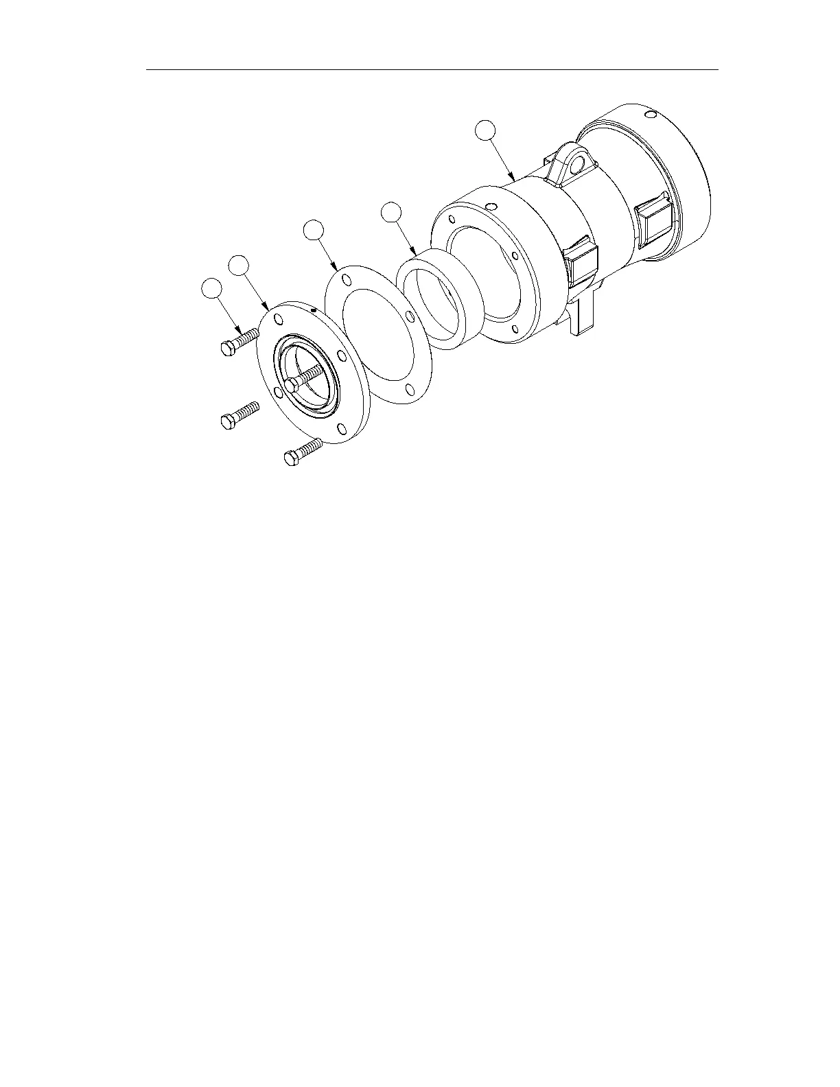
Fig 2.
6. Lightly grease or oil the inside bores of the Bearing Housing(2.3)
7. Insert Bearing Cup of Bearing(2.14) with the small I.D. facing towards the
outside of the Bearing Housing(2.3). Using a rubber mallet tap Bearing Cup into
Bearing Housing(2.3) till the Bearing Cup has been installed just past the lip of
the Bearing Housing(2.3) (See Fig 2.)
8. Place a 0.018”-0.020” Shim(2.4) onto Bearing Cover(2.5) and place assembled
components into position on Bearing Housing (2.3).(See Fig 2.)
9. Insert Hex Bolt(2.10) into assembled components and evenly tighten screws in a
crisscross pattern until Bearing Cover(2.5) is seated against Bearing Housing(2.3)
this will place the Bearing Cup into correct position. (See APPENDIX C for
cross-section)
10. Grease both Bearings(2.14) by hand, using grease specified in Table 5. Fill in
gaps between roller, roller cage, cone, and grease retainer.
11. Insert Shaft(2.1) assembly into Bearing Housing(2.3) threaded end first.
12. Place remaining Bearing Cup with small diameter facing out into housing and tap
it down using a rubber mallet until the Bearing Cup has been installed just past
the lip of the Bearing Housing(2.3).
13. Put Bearing Cover(2.5) with a 0.018”-0.020” Shim(2.4) on Bearing Housing(2.3)
14. Insert Hex Bolt(2.10) into assembled components and evenly tighten screws in a
crisscross pattern while rotating the shaft until shaft is hard to rotate and the is no
end play. This means the Bearing Cup is seated properly.
15. Grease Piston Rings(2.8) and install on each Bearing Labyrinth(2.6) with gaps
directly opposite of each other. (See Fig 3.)