24 | P a g e
4.3.2 Handbrakes
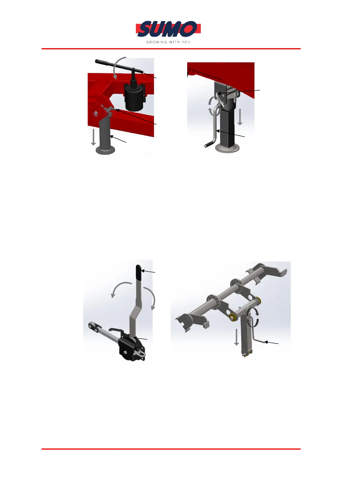
Handbrakes are tailored to match each machines construction, but generally
operated from a single crank lever or winding handle, usually positioned at the
front or rear of the machine. Before operating the handbrake ensure the
machine is fully supported by the Tractors handbrake. Fully apply handbrake by
pivoting/turning the lever in the required direction and ensure machine hold.
Before unhitching the tractor, ensure any stands are down and positioned
suitably. On winding handbrakes make sure to put securing cable to the handle
to ensure handbrake is not activated during travelling.
Examples:
4.3.3 Pneumatic Brakes
Pneumatic brakes generally consist of two brake cylinders (one per wheel), a
pressurised air tank, a set of configured brake levers (Both usually located at
the rear of the machine closest the axle/wheels), and an REV (Typically located
near the front of the machine). For connection details, see Hitching and tractor
connections section of this manual.