25 | P a g e
Example System:
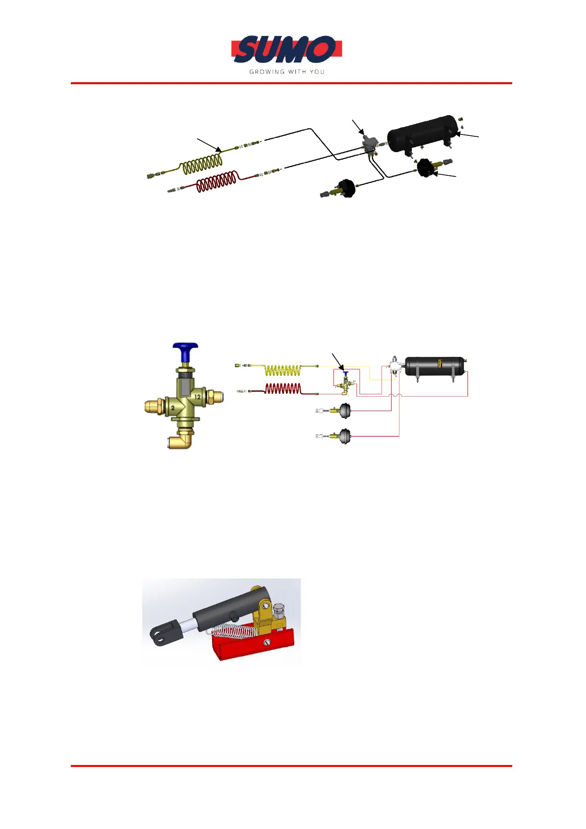
Our Homologated Pneumatic brake systems also include a Park/Shunt Valve
normally located at the front of the machine for temporary release of machine
brakes for shunting, if no tractor is available/connected. Press once only to
release brakes. Make certain to have a clear environment before release and
keep well clear of machine just in case it slides/moves unexpectedly. Never use
when machine is on an incline. Note: Brakes will lock if Park/Shunt Valve is
pressed twice.
Example System:
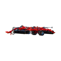
4.3.4 Hydraulic Brakes
Hydraulic brakes generally consist of two hydraulic cylinders attached directly
to the axle brake levers, typically located at the rear of the machine/mid-
machine axle. For connection details, see Hitching and tractor connections
section of this manual.
Example: