16
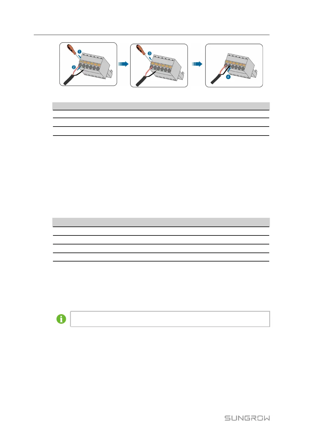
table 4-1 Terminal definition
MMaarrkk DDeeffiinniittiioonn
GND Connected to RS485 cable shield
A Connected to RS485–A, corresponding to upper-layer terminal
B
Connected to RS485–B, corresponding to lower-layer terminal
step 5 Gently pull the cable backwards to ensure firm connection.
step 6 Screw the "RS485" waterproof terminal at the bottom of COM100.
-- -- EEnndd
4.4.3 Optical Fibre (Optional)
PPrreeppaarraattiioonn bbeeffoorree IInnssttaallllaattiioonn
Before installation, prepare the required components. Components listed below are for
reference only, and the actual situation may differ.
NNoo..
CCoommppoonneenntt
1
Pigtail: 12-input single-mode ST, 600mm
2
Jumper: Single-mode single-core ST-SC, 500mm
3
ST flange
4 Network cable, 2,600mm
IInnssttaallllaattiioonn SStteeppss
step 1 Unscrew the waterproof terminal "Optical fiber ports", and lead the optical fibre through
the terminal.
step 2 Splice the optical fibre inside the splice box.
For details, contact SUNGROW.
step 3 Screw the waterproof terminal "Optical fiber ports".
-- -- EEnndd
4.4.4 AC 220V Connection
PPrreeppaarraattiioonn bbeeffoorree IInnssttaallllaattiioonn
• Before wiring AC 220V power supply, turn the micro circuit breaker to OFF position.
• Prepare the AC cable.
4 Electrical Connection User Manual