EasyManua.ls Logo

Sungrow EMS200 - Page 19

Sungrow EMS200
53 pages
Print Icon
To Next Page IconTo Next Page
To Previous Page IconTo Previous Page
Loading...
User Manual 5. Electrical Connection
13
Item
Remark
Name
Description
D
SD
SD card
interface
Function is reserved
E
Debug
Debugging
serial port
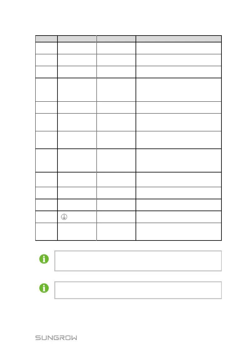
Used for debugging local controller
F
RST
Reset port
Used for hardware reset of local
controller
G
DO1~DO4
Digital output
Relay output ports, where the relay
specification is 250Vac/1A or
30V/1A
DO-DO4: Not assigned
H
PT1, PT2,
AI1~AI4
Analog input
Function is reserved
I
A1B1~A6B6
RS485
communicatio
n port
Supports 6 inputs of RS485, and
can be connected to slave devices
or background
J
CAN
CAN
communicatio
n port
Function is reserved
K
24V
DC24V power
supply port
Current ≤2.0A, and the
switch-mode power supply used for
this port should be insulated
intensely
L
AC
(100~240V)
AC power
supply port
Connected to 100~240Vac
(50/60Hz), and the current ≤0.5A
M
GPS/BDS
GPS antenna
port
Function is reserved
N
RF
Wireless
antenna port
Function is reserved
O
Grounding
hole
Connecting protection ground cable
P
PLCL1/L2
PLC
Communicatio
n port
Function is reserved
Digital input/output ports (DIN and DO1~DO4) are configured to
collect node data and control node communication.
The farthest communication distance of COM1 to COM6 (A1B1
A6B6) is no more than 1000m.

Table of Contents

Related product manuals