User Manual 5. Electrical Connection
17
Grounding hole of the local
controller
6.6 Power Supply Connection
The local controller supports DC24V DC input or AC100 to 240V (50/60HZ) AC
input. This section will take the AC power supply for example.
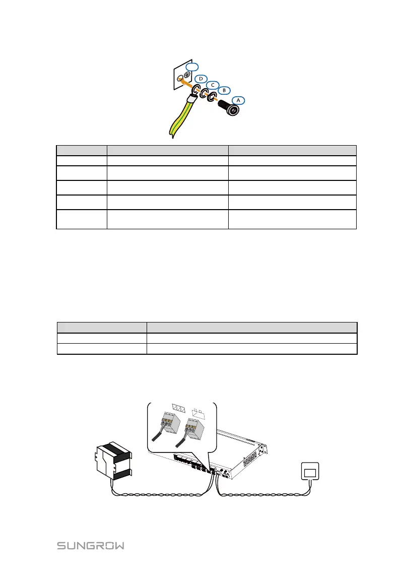
Step 1 Prepare power cables and phoenix terminal. Specifications of the AC &
DC cables are shown in the following table:
Recommended cross-sectional area
Cross-sectional area: 1mm
2
to 1.5mm
2
Cross-sectional area: 0.75mm
2
to1mm
2
Step 2 Remove the phoenix terminal at the power supply port of the local
controller, and crimp the power supply terminal.
Step 3 Insert the power supply terminal to the corresponding DC/AC power
supply port.