12
6 Electrical Connection
6.1 General Safety Regulations
Incorrect cable connections could damage the local controller or even
injure operators.
All cables must be undamaged, well insulated, appropriately sized, and
securely connected.
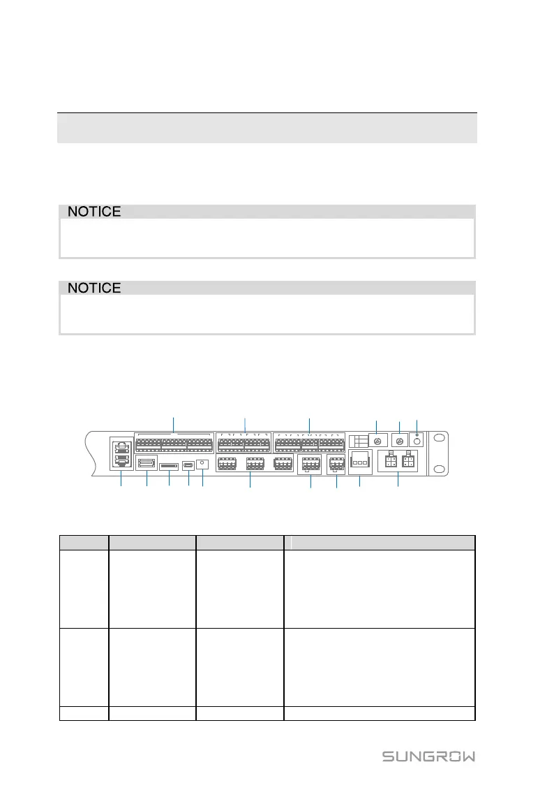
6.2 Terminal Introduction
A
B
C D E
G H
I LJF K
M N O
P
ETH2
ETH1
USB SD Debug RST
0V 1 2 3 4 5 6 7 8 9 10 11 12 13 14 1516 0V
DIN
1 2 3
DO1
1 3
DO2
1 3
DO3
1 3
DO4
2 2 2
A1 B1 A2B2 A3 B3A4 B4 A5 B5 A6 B6
+ - GND
PT1
+ - GND
PT2
+ -
AI1
+ -
AI2
+ -
AI3
+ -
AI4
H L
CAN
+ -
24V
AC(L) AC(N)
GPS/BDS RF
L1 L2
DO
1
2
3
NO
NC
COM
Tab. 6-1 Terminal description
ETH2 can be connected to local
controller via the switch, router, and
other devices; and ETH1 is used for
lower-layer devices (can be
connected to BCP, PCS, and the
like)
Node input port
DIN1: Not assigned
DIN2: Emergency stop node
DIN3-DIN5: Not assigned
DIN6-DIN13: Optional
DIN14-DIN16: Not assigned
Software upgrade interface