18
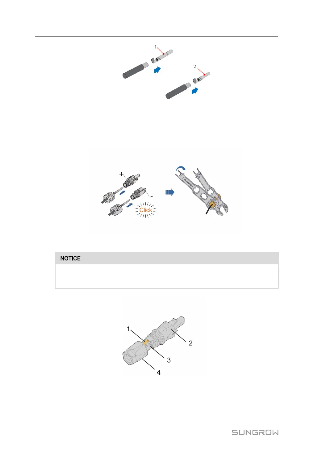
1: Positive crimp contact 2: Negative crimp contact
3. Lead the cable through cable gland, and insert the crimp contact into the insulator until it
snaps into place. Gently pull the cable backward to ensure firm connection. Tighten the
cable gland and the insulator (torque 2.5 N•m to 3 N•m).
Assembling the SUNCLIX Connector
During assembly, be careful not to contaminate, pull out, or shift, the seal in the
cable gland. A contaminated or shifted seal impairs strain relief and leak tightness.
figure 4-1 SUNCLIX Connector Components
1: Spring 2: Sleeve 3: Insert 4: Cable gland
1. Strip the insulation from the cable by 10mm - 15 mm.
4 Mounting User Manual