2 Product Introduction User Manual
10
2.3 Technical Description
2.3.1 Circuit Description
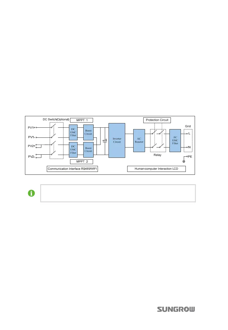
Fig. 2-5 shows the main circuit of inverter.
The inverter boost circuits raise input DC voltage. There are two string MPP trackers
to ensure the maximum power from PV arrays can be utilized. Then the inverter
circuit converts DC power to AC power. Meanwhile inverter is equipped with
protective circuit to guarantee its safety operation which can triggers the AC relay if
required.
Additionally, inverter provides RS485 and WiFi interface for communication. User
can look up running status and set parameters through LCD display panel.
Fig. 2-5 Main Circuit Diagram of inverter
The Main Circuit shown here is for SG4KTL-M and SG5KTL-M, there is only
one string of PV arrays in input area 2 of SG3KTL-M.
2.3.2 Functions Description
Inverter functions can be grouped as the following:
y
Conversion function
Inverter converts the direct current power into the alternating current power,
which conforms to the grid requirement of its installation country.
y
Data storage and display
Inverter archives essential data including running information and fault records,
and displays them on the integrated LCD display.
y
Parameters configuration
Inverter provides various parameters configuration for optimal operation.
 Loading...