Form 43343320
-26- Dec 2017
12.0) ATTACHING BURNER SCREEN – (200M BTU MODELS ONLY)
A burner screen is assembled with the burner. If necessary, the burner screen must be field adjusted as shown
below before operation of the heater.
1. Pull burner screen forward from the gas manifold and slide screen over burner until the tab stops against
the rear of the burner cup (approximately 4 - 3/16” from the burner box) as shown below.
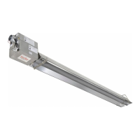
12.1) ATTACHING BURNER BOX ASSEMBLY
1. Attach the burner box and gasket to end of tube flange and secure with 1/4-20 locknuts.
2. Assemble the optional end reflector flush with the end of the main body reflector. Secure by sliding speed
clips onto the reflector edges. Evenly space the speed clips on the sides (one each side) and top (two
required) of the reflectors to provide a snug fit. Leave a 3" space between the end reflector and the burner
box assembly.
3. The heater can be mounted horizontally or at an angle of up to 45 degrees maximum from horizontal.
When angle mounting, the burner box unit must be positioned upright as shown below Failure to install the
control box in an UPRIGHT position will VOID the manufacturer’s warranty.