Questions? Call or Text +1 801-658-0015 • 3
With energy in a stored state, your Sunstone CDDP welder pro-
vides control over how the energy is released. The typical ca-
curve. But with adjustments to your welder’s controls, you will
be able to control how much energy is released in two pulses.
See Chapter 3 on page 10 for more information.
Weld Formation
Spot welding relies on metal resistivity (resistance) to heat and
fuse metal. A large current is passed through the work piece
metal. Energy is dissipated due to metal resistance in the form
of heat which melts and fuses the weld materials. There are two
phases to the melting process. The welder must overcome both
the material contact resistance and the bulk resistance of the
material.
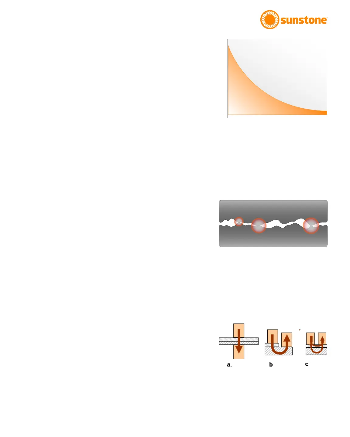
On the micro-scale, material surfaces are rough and only con-
metal bridges melt, allowing other bridges to come into contact
to continue the melting process. When all of the bridges have
Tips
WELD PRESSURE
Several other factors play a part in the contact resistance. The
larger the contact resistance the hotter the resultant weld.
On the micro-scale, contact resistance is reduced when more
-
ing more electrode pressure creates more metal bridges. This
results in a lower contact resistance and a cooler weld. Con-
versely, light electrode pressure results in less metal contact,
higher resistance, and a hotter weld. An appropriate amount of
pressure should be used to insure good weld strength.
ELECTRODE CONFIGURATIONS
resistance welding. Figure 3.3a is called a direct weld. Current
is passed from one electrode through both work pieces and
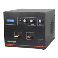
POWER
TIME
Figure 3.1. Sample capacitor discharge curve.
Figure 3.3. Examples of resistance welding
electrode congurations. A: Direct. B: Step. C:
Series.
Figure 3.2. Surface roughness limits surface-to-
surface contact. More contact points result in a
lower contact resistance.