Installation
NT 10000...NT 12000 21
NOTE
For lines with a cable sheath diameter from 16 to 20 mm, the cable gland must
be adapted accordingly. To do this, cut out the inner section of the blue sealing
ring.
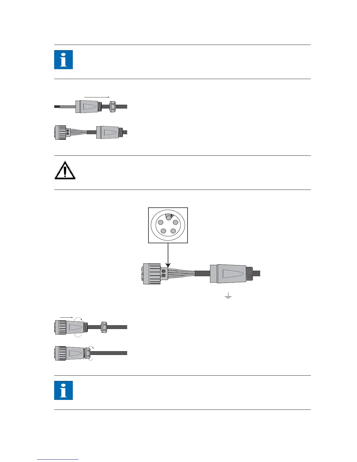
2. Slide the cable gland and the plug housing onto the cable.
3. Connect the cable ends to the plug terminals in accordance with the pin as-
signment. Tightening torque: 0.7 Nm.
CAUTION
Observe the pin assignment of the AC bayonet connector. An incorrect assign-
ment can result in the unit being destroyed. The diagram shows the connections
inside the AC connector, as indicated by the cut-out at the PE connection.
1 = N (neutral conductor)
2 = L1 (feed-in phase)
3 = L2 (feed-in phase)
4 = L3 (feed-in phase)
= PE (protective earth conductor)
4. Screw plug housing to plug. To do this, push the outer ring of the plug to-
ward the connector housing. Tightening torque: 1-2 Nm.
5. Tighten the cable gland.
Tightening torque for cable sheath diameters between 13 and 20 mm: 6 to
8 Nm
NOTE
Make sure the line is provided with a strain relief device. When using cables
with a diameter of less than 16 mm, the line must be relieved just behind the
connector.
1
2
4
3
The diagram shows the
connections inside the AC
connector, as indicated by the
cut-out at the PE connection.