Installation
22 NT 10000...NT 12000
4.3 Installing the communication equipment
The interfaces are located behind the weatherproof connection box on the un-
derside of the Solar Inverter.
To open the connection box, loose the centre screw. Then carefully pull way the
box toward the front.
After you have installed the connection cable, close the box again by guiding
the locking hooks into the notches in the housing and then pressing the box
onto the housing.
Retighten the mounting screw.
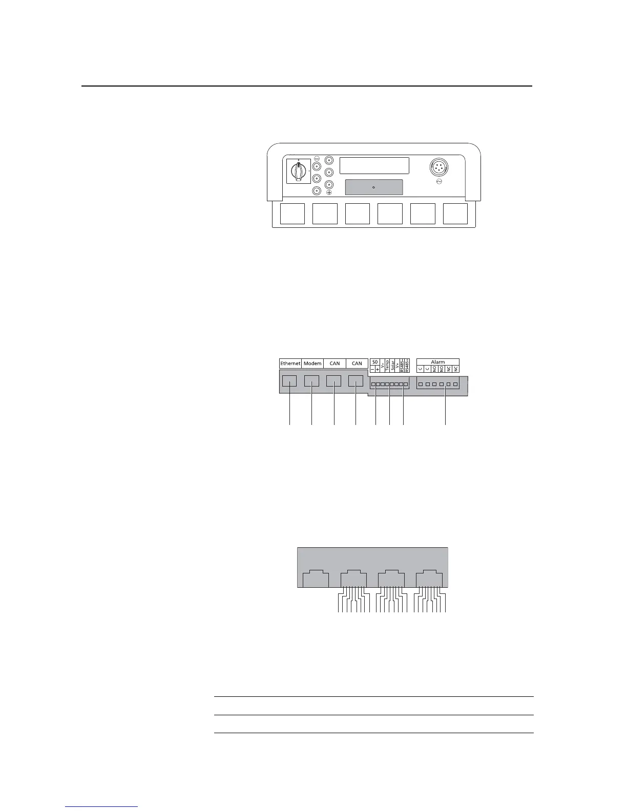
Interface overview
1 Ethernet connection
2 Modem connection
3CAN IN
4CAN OUT
5 S0 interface (pulse output, e.g. for
large display)
6 Terminal for temperature and irra-
diance sensor
7 RS485 interface
8 Terminal for alarm relay
Pin assignment
The connectors for the CAN interfaces CAN IN and CAN OUT and for the modem
interface have the following pin assignment:
CAN and modem