Installation
NT 10000...NT 12000 27
Connecting the alarm relay The Solar Inverters are equipped with a potential-free alarm relay as standard.
The relay can be designed as a make-contact element or as a break-contact ele-
ment and is actuated for all malfunctions signalled by the device. This ensures
fast, reliable indication of a possible fault in the PV system on site. For PV sys-
tems with several Solar Inverters the individual relays can be switched in parallel
and connected via a common indicator lamp.
The main unit also signals faults from other units in the CAN network via the
alarm relay. It is therefore sufficient for simple alerting to connect the alarm re-
lay of the main unit.
CAUTION
The alarm relay is designed for 230 V/2 A. Higher outputs/voltages can result in
the relay being destroyed. The connected signalling unit must be fused separa-
tely. The terminals are intended for a cable cross-section of 0.2 mm
2
to 1.5 mm
2
.
When dimensioning the cross-section, also take the current consumption of the
connected signalling unit into account.
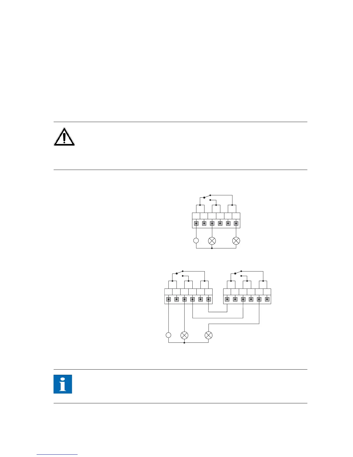
Wiring diagram for a single unit
Wiring diagram for several units
1 Indicator lamp, red 2 Indicator lamp, green
NOTE
The Solar Inverter is supplied by the feed phases from the AC grid. If all feed
phases fail simultaneous, the alarm relay cannot respond, despite the fact that
there is a fault.