24 25
※ 4.4 External ground connection
Ground terminal connection steps:
① The external grounding terminal is located in the lower right side of the inverter.
② Fix the grounding terminal to the PE wire with a proper tool and lock the grounding
terminal to the grounding hole in the lower right side of the inverter, as shown in Figure
4-13.
③ The cross-sectional area of the external grounding cable is 4mm
2
.
Danger
Do not connect the N-wire as a protective ground wire to the inverter casing. Otherwise,
it may cause electric shock.
Attention
Good grounding is good for resisting surge voltage shock and improving EMI perfor-
mance. Inverters must be well-grounded.
For a system with only one inverter, the PE cable needs to be grounded.
For a multi-inverter system, all inverters PE wires need to be connected to the same
grounding copper bar to ensure equipotential bonding.
Figure 4-13 Grounding terminal connection
4 Installation
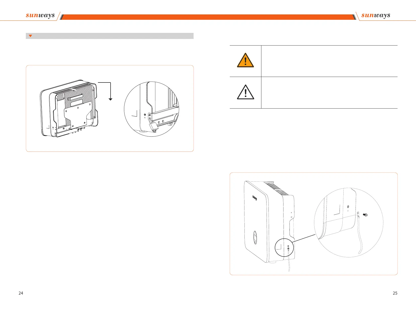
Lift the inverter, hang the back rail on the xed wall bracket carefully. Screws the inverter to
the L-shaped plate (The lock is purchased separately). See Figure 4-12 for details:
4.3.2 Mounting the inverter
Figure 4-12 Mounting the inverter
4 Installation