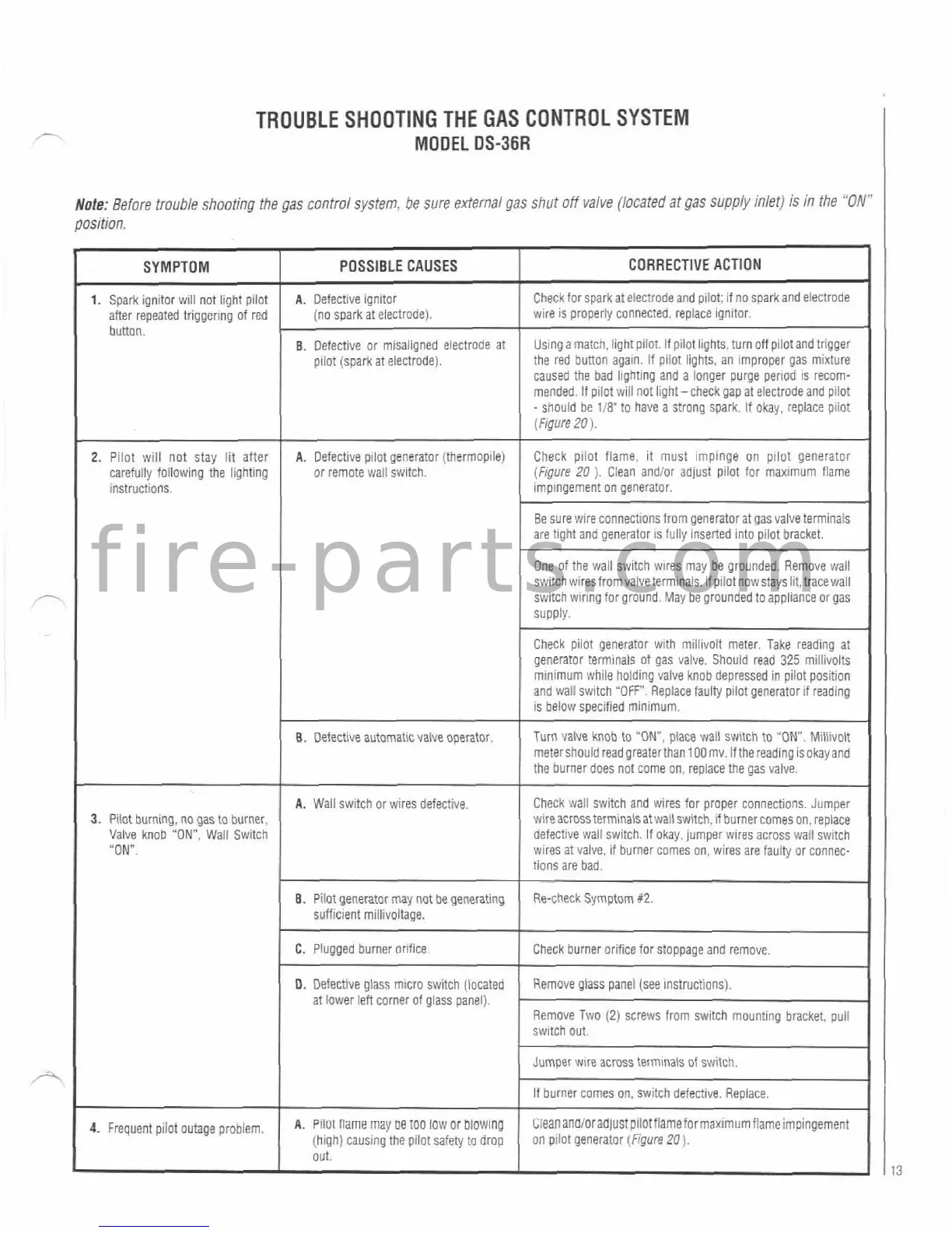
TROUBLE SHOOTING THE GAS CONTROL SYSTEM
MODEL
DS-36R
Note:
Before trouble shooting the gas control system. be sure external gas shut off valve (located at gas supply inlet) is in the
"C
-
A
CORRECTIVE ACTION
Check for sparkat electrode and p~lot; if no sparkand electrode
wire is properly connected, replace ignitor.
Using a match. light pilot. If pilot lights, turn off pilot and trigger
the red button again.
If pilot lights, an Improper gas mixture
caused the bad
lhghting and
a
longer purge period is recom-
mended. If pilot will not light -check gap at electrode and pilot
-
should be 1/8'to have a strong spark. If okay, replace pilot
(Figure
20).
Check piiot flame, it must impinge on pilot generator
(Frgure
20
).
Clean and/or adjust pilot for maximum flame
impingement
on generator.
Be sure wire connections from generalor at gas valve terminals
are tight and generator
1s fully nserled into pilot bracket.
One of the wall
swltch wlres may be grounded. Remove wall
switch wiresfromvaive terminals.
If pilot nowstay slit, tracewall
switch wiring for ground. May be grounded to appliance or gas
Supply.
Check piiot generator with millivolt meter. Take reading at
generator terminals of gas valve. Should read
325
millivolts
minimum while
holdlng valve knob depressed in pilot position
and
wall switch
"OFF".
Replace faulty pilot generator it reading
is below specified minimum.
Turn valve knob
to
"ON,
place wall switch to "ON. Miilivolt
metershould
readgreaterthan100mv. Ifthe reading isokay and
the burner does not come on, replace the gas
valve.
Check wall switch and wires for proper connections. Jumper
wireacrossterminalsatwallswitch. if burner
corne~on. replace
defective wall switch. If okay, jumper wires across wail
switch
wires at valve, if burner comes on, wires are faulty or connec-
tions are bad.
Re-check Symptom
X2.
Check burner orifice for stoppage and remove.
-
~p
Remove glass panel (see instructions).
Remove Two
(2)
screws from switch mounting bracket. pull
switch
out.
Jumper wlre across
terminals
of switch.
if burner comes on, switch defective.
Repiace.
c;ieananaioraa~ustp~lotflameformax~mumflameimpingement
on pilot generator (Figure
20).
position.
SYMPTOM
1.
Spark ignitor will not light pilot
after repeated
triggering
of red
button.
2.
Pilot will not stay lit after
carefuily following the lighting
instructions.
3.
Pilot burning, no
gas
to burner,
Valve knob "ON", Wall Switch
"ON.
4.
~~~~~~~t pilot
outage
problem,
POSSIBLE CAUSES
A.
Defective ignitor
(no spark at electrode).
B.
Defective or misaligned electrode at
pilot (spark at electrode).
A.
Defective p~iot generator (thermopile)
or
remote wail swltch.
8.
Defective automaticvalve operator.
A.
Wall switch or wlres defective.
8.
Pilot generator may not
be
generating
sufficient
millivoltage.
C.
Plugged burner orlfice~
-
0.
Defective glass micro switch [located
at lower left corner of glass panel).
A.
~ilut flame may
oe
too low or blowing
(high) causing the piiot safety to drop
out.
 Loading...