Do not use this appliance if any part has been
-
under water, Immediately call a qualified ser-
vice technician to inspect the appliance and to
replace any pans of the control system that
have been under water.
ASSEMBLY STEPS
The typical sequence of installation foilows.
however,each installation isunique resultingin
variations to those described.
This appliance must be vented through an
1.
Construct appliance framing
outside wall and must not be connected to a
If the appliance is to be elevated above floor
level, a soiid continuous platform must be
constructed.
chimney or flue
sewing a soiid fuel burning
appliance.
LOCATION AND CLEARANCES
The header may rest on the top metal spacers.
but must not be notched to fit around them.
2.
Routegas supply line toappliance location.
3.
Position appliance and install the vent ter-
mination.
On
flatwall installations. two (2) studs (on
16'
centers. as illustrated) should be provided at
the rear structure to accommodate installation
of the vent termination.
In selecting the location, the esthetic and
func-
4.
Make connection
gas Supply and install
FRAMING DIMENSIONS
tional uses of the aonliance are orimaw con-
the log and burner assembly.
,
.
,
~~
cerns. However, thevent location and access to
the fuel supply are also important. Consider-
ation should be given to
traffic ways, furniture.
draperies, etc., due to elevated surface tem-
peratures. The location should also be free of
electrical or plumbing lines. Building codes
limit vent location in specific areas. Generally,
a Vent may not be located above. or within
6'
(1.8 m) of a gas regulator. Refer to
FigureGfor
exterior vent location limitations. Check local
codes for requirements.
Minimum clearances lo combustibles are:
,-
Appliance sides and back
-
0"
floor
-
0"
adjacent wall
-
0'
celiing
-
37-112'
(95
3
cm)
Vent
top
-
3'
(76
mm)
sides
-
1-314"
(44
mm)
bottom
-
1'
(25
mm)
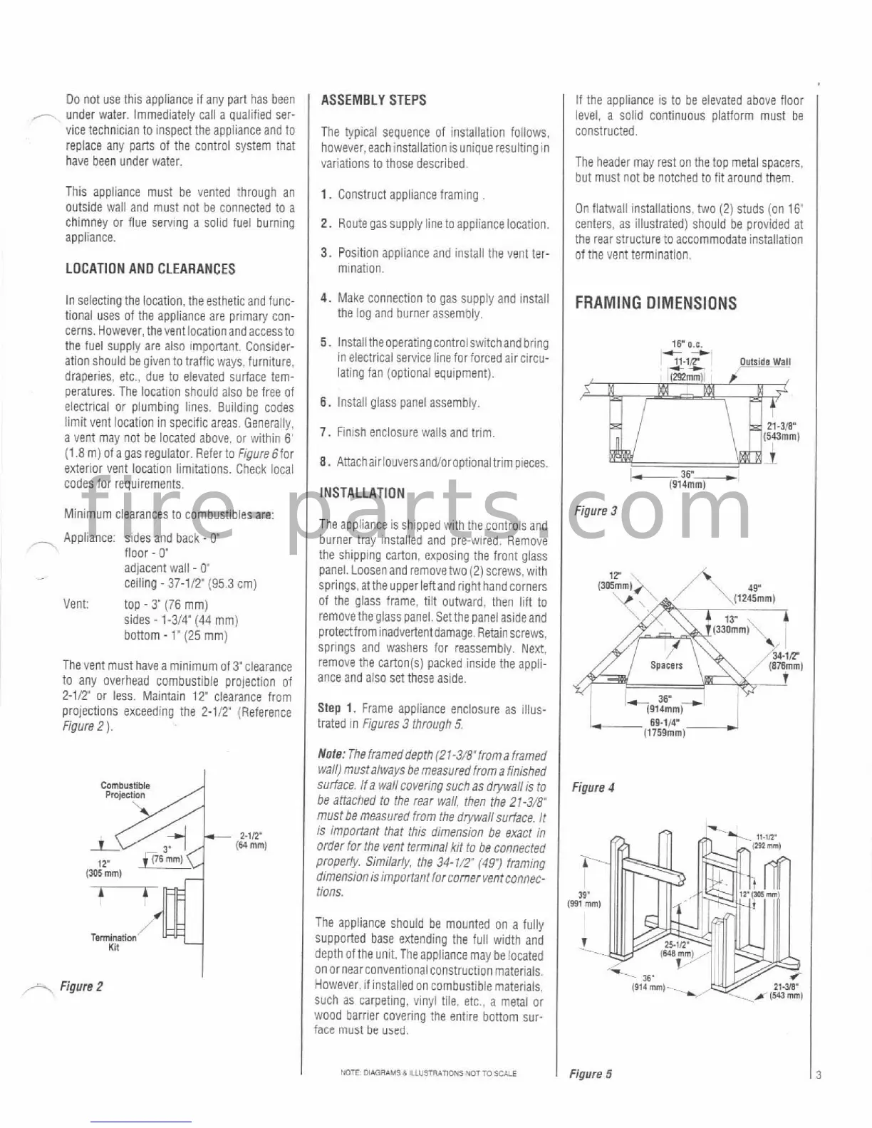
The vent must have a minimum
Of3"Clearance
to any overhead combustible projection of
2-112" or less. Maintain
12'
clearance from
projections exceeding the
2-112" (Reference
Figure 2
)
.
+-.
Figure
2
5.
Install theoperating controlswitchand bring
in electrical service line for forced air circu-
lating fan (optional equipment).
6.
install giass panel assembly.
7.
Finish enclosure walls and trim.
8.
Anachairlouversandioroptionaltrimpieces.
INSTALLATION
The appliance is shlpped with the controis and
burner tray instailed and pre-wired. Remove
the shipping carton. exposing the front glass
panel. Loosen and remove two (2) screws. with
springs,atthe
upperieftandrighthandcorners
of the glass frame, tiit outward. then lilt to
removethe glass panel.
Setthe panel asideand
protectfrom inadvertentdamage. Retainscrews.
springs and washers for
reassembly. Next.
remove the
carton(s) packed inside the appii-
ance and also set these aside.
Step
1.
Frame appliance enclosure as illus-
trated in
Figures 3 through
5,
Note: The frameddeprh (21-3i8"froma framed
wall) mustalways be measured from a finished
surface. If a wall covering such as
drywall is to
be
attached to the rear wall, then the 21-3/8~
must be measured from the drywall surface. It
is important that this dimension be exact in
order far the vent
term~nal kit to be connected
properly.
Similarly. the 34-71.?
(491
framing
dimension is important forcorner
ventconnec-
t10ns.
The appliance should be mounted on a fully
supported base extending the full width and
depth
ofthe unit. Theappliance may be located
on or nearconventional construction materials.
However, if installed on combustible materials,
Such as carpeting, vinyl tile, etc.. a metal or
wood barrier covering the entire bottom sur-
face
must
be
used.
15.
O.C.
l%.,i?
m*
+
Outside
Wall
Figure
3
Figure
4
I
NOTE
OWGRAMSb
ILIU5TR*mONS
WTTO
SCALE
I
Figure
5