Step
6.
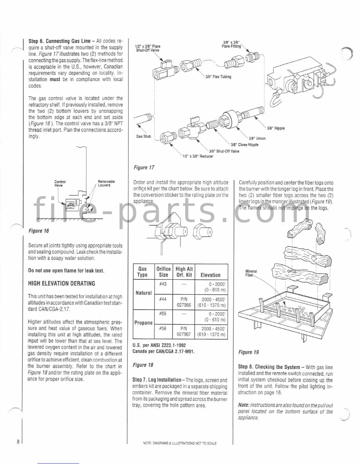
Connecting Gas Line -All codes re-
,
-.
quire a shut-off valve mounted in the supply
iine. Figure
17illustrates two (2) methods for
connectingthegassupply.Theflex-linemethod
is acceptable in the
U.S.,
however. Canadian
requirements vary depending on locality. In-
stallation must be in cornpiiance with
local
codes.
The gas control valve is located under the
refractory shelf.
If previously installed, remove
the two
(2)
bottom louvers by unsnapping
the bottom edge at each end and set aside
(Figure
16).
The control valve has a 318' NPT
thread inlet port.
Plan the connections accord-
ingly.
Figure
76
Secure all joints tightly using appropriate tools
andsealing compound.
Leakchecktheinstalla-
tion with a soapy water solution.
I
Do not use open flame for leak test.
I
HIGH
ELEVATION OERATING
This unit has been tested for installation at high
altitudesinaccordance
withCanadian teststan-
dard CANICGA-2.17.
Higher aititudes affect the atmospheric pres-
sure and heat
value of gaseous fuels. When
installing this unit at high altitudes, the rated
input wili be lower than that at sea level. The
lowered oxygen content in the air and lowered
gas density require installation of a different
orifice to achieve efficient. clean combustion at
the burner assembly. Refer to the chart in
Fipure 18andIor the rating plate on the appii-
ance for proper orifice size.
Figure
17
Order and install the appropriate high altitude
orifice kit perthechart below. Be suretoattach
the conversion stickerto the rating
piateon the
appliance.
l~;e~o;ri~~ig~~t~
1
Size Orl. Kit Elevation
0
-
2000'
Natural
(0-610
m)
U.S.
per
ANSI 2223.1-1992
Canada
per
CANICGA 2.17-M91.
Figure
18
Step7. Loglnstallatian-The logs, screenand
embers
kitare packaged ina separateshipping
container. Remove the mineral fiber rnateriai
frornits packagingandspread acrossthe burner
tray, covering the
hole pattern area.
NOTE
OIAORAMSd ILLUSTRATIWS
NOTTOSCALE
I
Carefully position and centerthe fiber logs onto
the burnerwith thelongerioginfront.
Placethe
two (2) smaller fiber logs across the two (2)
lower
log sin the manneriilustrated (Figure
19).
The flames should not impinge on the logs.
v
Figure
19
Step
8.
Checking the System
-
With gas iine
installed and the remote switch connected, run
initial system checkout before closing up the
front of the unit. Follow the pilot lighting in-
struction on page
16.
Note:
lnstructlonsarealso foundon thepuliout
panel located
on
the bottom surface of the
appl~ance
I'