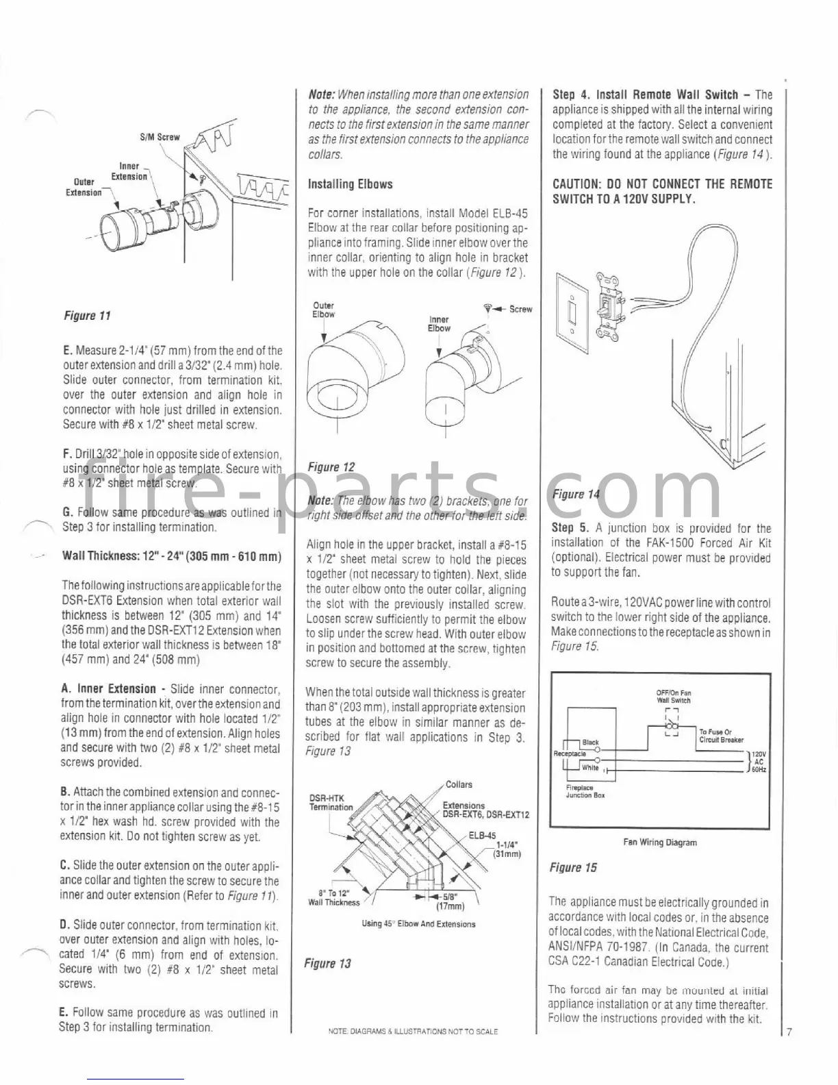
Figure
11
E. Measure2-114'(57 mm) from theend ofthe
outer extension and drill a 3132' (2.4 mm) hole.
Slide outer connector, from termination kit.
over the outer extension and align hole in
connector with hole just drilled in extension.
Secure
with #8 x 112'sheet metal screw.
Note: When installing more than one extension
to the appliance. the second extension con-
nects to the first extension in the same manner
as the first
extensfon connects to !he appliance
collars.
Installing Elbows
For corner installations, install Model ELB-45
Elbow at the rear collar before positioning
ap-
plianceintoframing. Slide innerelbow overthe
inner collar, orienting to align hole in bracket
with the upper hoie on the collar (Figure 12).
Step
4.
Install Remote Wall Switch
-
The
applianceis shipped
withall the internal wiring
completed at the
factoly. Seiect a convenient
location
forthe remote wall switchand connect
the wiring found at the appliance (Figure 14
1.
F.
Drill 3/32 hole in oppositesideof extension,
using connector hole as template. Secure with
#8 x 112'sheet metal screw.
G.
Follow same procedure as was outlined in
Step
3
for installing termination.
WallThiCkneSS:
12"-24"(305
mm
-
610
mm)
CAUTION: 00 NOT CONNECT THE REMOTE
SWITCH TO
A
120V
SUPPLY.
Figure
12
Note: The elbow has two (2) brackets, one for
rightside offsetand the other for theleftside.
Align hole in the upper bracket, install a X8-15
x
1/T sheet metal screw to hold the ~iece~
Figure
14
Step
5.
A junction box is provided for the
installation of the FAK-1500 Forced Air Kit
(optional). Electrical power must be provided
together (not
necessaw totighten). ~ei, slide
to support the fan.
ThefollowinginstructionsareaPPlicableforthe
the outer elbow onto the outer collar, aligning
DSR-EXT6 Extension when total exterior wail
the slot with the oreviouslv installed screw
R0utea3-wire, l20VAC powerlinewithcontrol
thickness is between 12" (305
mm) and
14'
(356 mm) and the DSR-EXT12 Extension when
the total exterior wail thickness is between
18"
(457
mm) and 24" (508 mm)
A.
Inner Extension
-
Slide inner connector,
from the termination kit, overthe extension and
align hole in connector with hole located
112'
(13 mm)from the end of extension. Align holes
and secure with
two (2) 88
x
112' sheet metal
screws provided.
8.
Attach the combined extension and connec-
tor in the innerappliance collar using
the#-1 5
x
112' hex wash hd. screw provided with the
extension kit.
Do not tighten screw as yet.
C. Slide the outer extension on the outer appli-
ance collarand tighten
thescrew to secure the
inner and outer extension (Refer to Figure
11).
When thetotal outside wallthickness is greater
thanF? (203 mm).installappropriate extension
tubes at the elbow in similar manner as de-
scribed for fiat wall applications in Step
3.
figure 13
~ ~
~
,
-~~~~
--
..
.
.~.
Loosen screw suftjciently to permit the elbow
to slip under the screw head. With outereibow
in position and bottomed at the screw, tighten
screw to secure the assemblv.
Rnpm
lvma
sox
L
an
Wiring
Diagram
Figure
15
switch to the lower right side of the appliance.
Makeconnectionstothereceptacleasshownin
Figure 15.
The appliancemust beelectricallvarounded in
appliance installation
or at any time thereafter,
E.
Follow Same procedure as was outlined in
Follow the instructions provided with the kit.
Step 3 for installing termination.
VCTE
OIAGRAMS
A
LLUSTRAPONS
NO7
TO
SCALE
0.
Slide outer connector, from termination kit.
over outer extension and align with holes,
lo-
-
cated 114'
(6
mm) from end of extension.
Secure with two (2)
#8
x 112' sheet metal
screws.
,
. . .
. .
.
. .
,
UNng
45':
Elbar
And
Extensions
13
accordance with local codes or. iniheabsence
of local codes. withthe National EiectricalCode.
ANSIINFPA 70-1987. (In Canada. the current
CSA
C22-1 Canadian Electrical Code.)
Thc
far~ed
air
fan
mav
be inuuritrd
at
initial