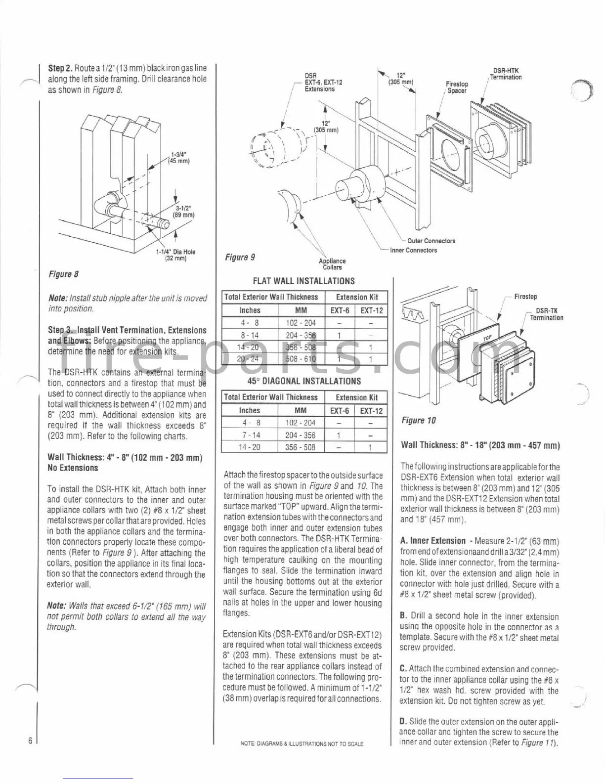
Step2. Routea112'(13mm) blackirongasline
-
along the leftsideframing. Driii clearance hole
as shown in
Figure
8.
MR
OSR-HTK
Termlnahon
-
UT4.
UT-12
Firertop
I
,'
Enensloor
r
Spacer
(32
mm)
Figure
8
Note:
Installstub nipple affer the unit is moved
into position.
Step3. Install Vent Termination, Extensions
and Elbows: Before positioning the appliance,
determine the need for extension kits.
The DSR-HTK contains an external termina-
tion, connectors and a
firestop that must be
-sed to clnnec: a~recrly :o 1-15 applarc? Nhen
I
lural wall thlcrtness s oerween
@
102
nrr,
ano
8'
(203 mm). Additional extension kits are
required if the wall thickness exceeds
8"
(203 mm). Refer to the following charts.
Walt Thickness:
4'-
8'
(102
mm
-
203
mm)
No Extensions
To install the DSR-HTK kit, Attach both inner
and outer connectors to the inner and outer
appliance collars with two
(2)
#8
x
112'
sheet
metal screws per collarthatare provided. Holes
in both the appliance collars and the termina-
tion connectors properly
locate these compo-
nents (Refer to
Figure
9
).
After attaching the
collars, position the appliance in its final loca-
tion so that the connectors extend through the
exterior wall.
Note:
Walls that exceed
6-I/.
(765
mm) will
not permit
both
collars to extend aN the way
through.
\\
Louts
ConMdor.
Figure
9
'+\
lmr
~onnecmn
A
pllance
!011am
FLAT WALL INSTALLATIONS
Total Exterior Wall Thickness Extension Kit
Inches
EXT-6
EXT-12
204
-
356
14-20
356-
508
-
20-24 508
-
610
45"
DIAGONAL INSTALLATIONS
1
Inches
1
MM
I
MT-fi
EXT-12
4
8
1
in?-7M
I
-
I
-
Attach thefirestopspacerto theoutsidesurface
of the wail as shown in
Figure
9
and 10 The
termination housing must
be
oriented with the
surfacemarked "TOP" upward. Align
thetermi-
nation
extensiontubeswiththeconnectorsand
engage both inner and outer extension tubes
over both connectors. The
DSR-HTKTermina-
tion requires the application of a liberal bead of
high temperature caulking on the mounting
flanges to seal. Slide the termination inward
until the housing bottoms out at the exterior
wall surface. Secure the termination using 6d
nails at holes in the upper and lower housing
flanges.
Extension Kits
(DSR-EXTGandlor DSR-EXT12)
are required when total wall thickness exceeds
8"
(203 mm). These extensions must be at-
Figure
10
Wall Thickness:
8"
-
18"
(203
mm
-
457
mm)
1
Thefoliowing
instructionsareapplicableforthe
DSR-EXT6 Extension when total exterior wall
tached to the rear appliance collars instead of
the termination connectors. The following pro-
cedure must befollowed. A minimumof
1-11?
(38 mm) overlap is requiredforall connections.
Ihll:klless
s
o:?Neen 8'(203 mm! ano
12'(305
mm an0 !he DSZ-EX72 Extels on wnen tnra
.
exterlorwall thlcknessis between 8"(203 mm)
and
18'
(457
mm).
A.
Inner Extension -Measure 2-112" (63 rnm)
from endof
extensionaanddriIia3/32"(2.4mm)
hole. Slide inner connector, from the termina-
tion kit, over the extension and align hole in
connector with hole just drilled. Secure with a
R8 x 112' sheet metal screw (provided).
B.
Drill a second hole in the inner extension
using the opposite hole in the connector as a
template. Secure with
the#8xtITsheet metal
screw provided.
C.
Attach the combined extensionand connec-
tor to the inner appliance collar using the
#8
x
112' hex wash hd. screw provided with the
extension kit. Do not tighten screw as yet.
*
D. Slide the outer extension on the outerappli-
ance collar and tighten the screw to secure the
inner and outer extension (Referta
Figure
11).