When first lighting the appliance, it will take a
.-
few minutes for the line to purge itself of air.
Once purging iscomplete, the pilot and burner
will
lightand operateas indicated inthe instruc-
tion manual. Subsequent lightings of the appli-
ance will not require such purging. Inspect the
pilotflame(removelogs, if necessary, handling
carefully).
The
flame slould oe steady, no' tltlng or llrat-
~na.Flameshot~~o be,-~~e~~icolor wlh
Pxe?
cl
orange at the outer edge
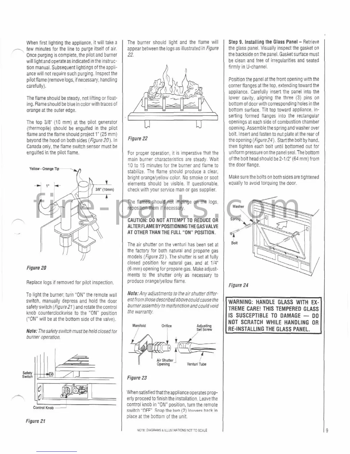
The top 3i8'
(10
mm) at the pilot generator
(thermopile) should be engulfed in the pilot
flameand the flame should project
1'
(25
mm)
beyond the hood on both sides
(Figure20). In
Canada only, the flame switch sensor must be
engulfed in the pilotflame.
Figure
20
Replace logs if removed for pilot inspection.
To light the burner; turn "ON" the remote wall
switch, manually depress and hold the door
safetyswitch
(FigureZl) and rotate thecontrol
knob counterclockwise to the
"ON"
posltion
("ON"
will be at the bottom side of the valve).
Wale: Thesafetyswitch mustbe held closed for
burner operation.
I
Comml
Kmb
-
Figure
21
The burner should light and the flame will
appear between the logsas iilustrated in
Figure
22.
Figure
22
For proper operation,
it
is imperative that the
main burner characteristics are steady. Wait
10
to 15 minutes for the burner and flame to
stabilize. The flame should produce a clear,
bright orangeiyellow color. No smoke or soot
elements should be visible. If questionable,
check with your service man or gas supplier.
The flames should not impinge on the logs.
reposition them if necessary.
CAUTION:
DO NOT ATTEMPT TO REDUCE OR
ALTER
FLAMEBY POSITIONINCTHEGASVALVE
AT OTHER THAN THE FULL "ON" POSITION,
The air shutter on the venturi has been set at
the factory for both natural and propane gas
models
(Figure23). The shuner is set at fully
closed position for natural gas, and at
114"
(6
mm) opening for propane gas. Makeadjust-
ments to the shuner only as necessary to
produce orangeiyellow flame.
Note: Any adjustments to
theair shutter differ-
entfrom
thosedescribedabovecouldcause
the
burnerassembly
to
malfunction andcouid void
the warranty
Figure
23
I
Whensatisfiedthattheappliance
operatesprop-
erly proceed to finish the installation. Leavethe
control knob in
"ON"
position, turn the remote
switch
"OFF
Sna~
the
two
(2)
lauuerr
hack
in
piace at the bottom of the unit.
NOTE:
OAGRAMS
d
ILLUSTRATIONS
NOTTO
SCALE
I
Step
9.
Installing the Glass Panel
-
Retrieve
the glass
panel. Visually inspect the gasket on
the backside on the panel. Gasket surface must
be
clean and free of irregularities and seated
firmly in
U-channel.
Position the panel at the front opening with the
corner flanges at the top, extending toward the
appliance. Carefully
insert the panel into the
lower cavity, aligning the three
(3)
pins on
bottom of door
wlth
corresponding
holes in the
bottom surface. Tilt top toward appliance, in-
serting formed flanges into the rectangular
openings at each side of combustion chamber
opening. Assemble the spring and washer over
bolt. Insert and fasten to nut
plateat the rear of
the opening (Figure24). Startthe boltby hand,
then tighten each bolt until bottomed out for
uniform pressure
onthe panel seal. The bottom
of the bolt head should be
2-112'(64 mm) from
the door flange.
Make sure the
boltson bothsides are tightened
eauaily to avoid torquing the door.
Figure
24
TREME
CARE! THIS TEMPERED GLASS
IS SUSCEPTIBLE TO DAMAGE
-
DO
NOT
SCRATCH WHILE HANDLING OR
9