25
Chapter 2: Installation
BAR CODE
COM2
DESIGNED IN USA
A2SDV-8C-TLN5F
REV:1.02
JIPMB1
JMD2
JMD1
JTGLED1
JPW1
JPI2C1
JSD1
SRW2
SRW3
SRW4
SRW1
JUIDB
JPL1
1
JWD1
JPG1
JBR1
JPME2
JI2C1
JI2C2
DIMMB1
DIMMB2
DIMMA1
DIMMA2
LED1
1
JD1
JSMB1
JBT1
JPH1
JPV1
FANB
JTPM1
JNCSI1
JL1
JRT4
1
JRT3
I-SATA1 I-SATA0
UIDLED1
CM CODE
LEDBMC
eUSB
ON
PWR
JF1
RST X
OH/FF
2
NIC NIC
1 LED
HDD
LED
X
PWR
NMI
ALWAYS POPULATE DIMMx1 FIRST
CPU SLOT6 PCI-E 3.0 X8
CPU SLOT7 PCI-E 3.0 X8
VGA
KEY-M PCIE3/SATA3
KEY-B SATA3/USB3
COM1
LAN1(IPMI_LAN)
LAN5
CPU
USB6(3.0)
USB2/3(3.0)
USB0/1(3.0)
USB 4/5
LAN3
FAN4 FAN3
FAN2 FAN1
LAN4/
LAN2/
FANA
SATA DOM POWER
BT1
JF1
BMC AST2400
JPTG1
JSEL1
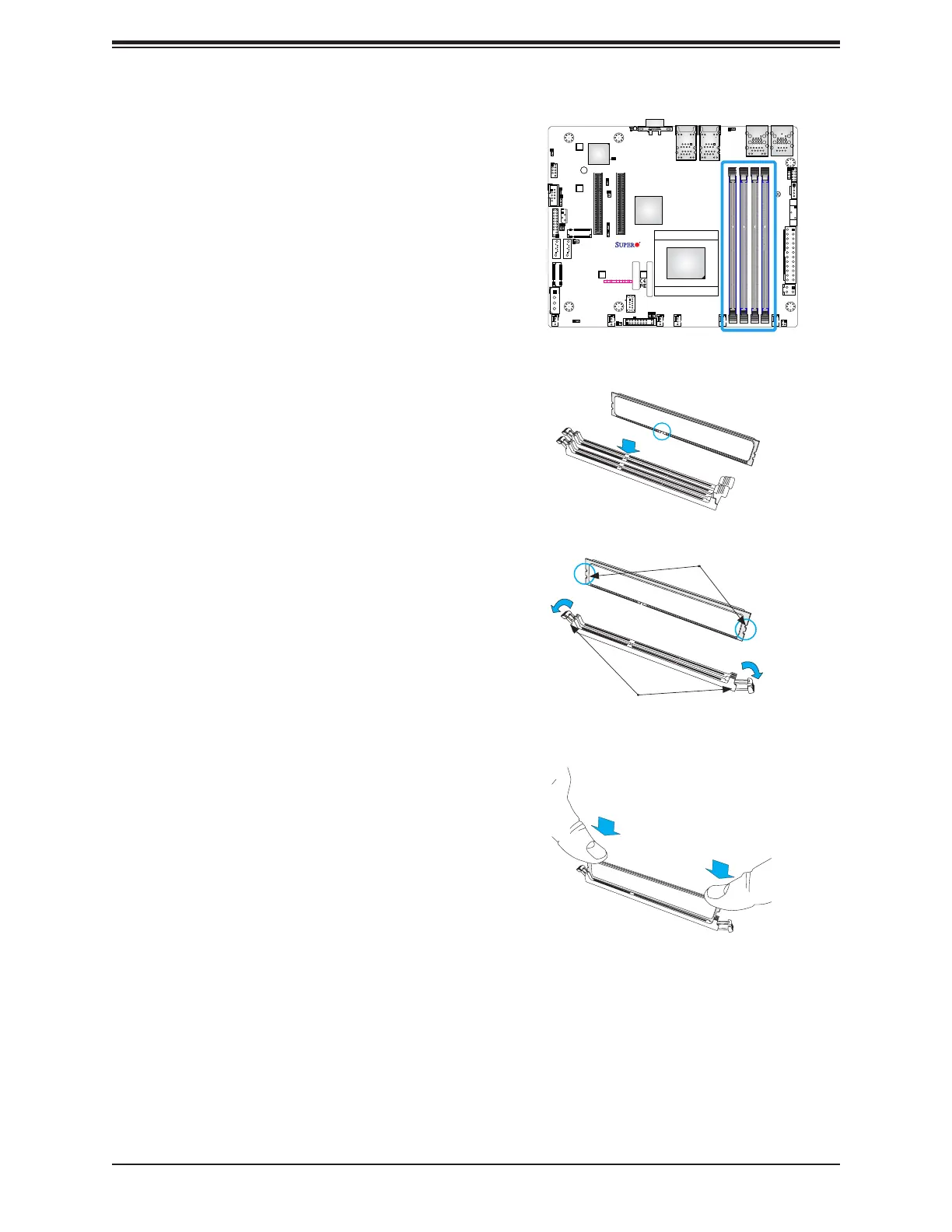
DIMM Installation
1. Insert the desired number of DIMMs into
the memory slots, starting with DIMMA1,
DIMMB1, DIMMA2, DIMMB2. For best
performance, please use the memory
modules of the same type and speed in
the same bank.
2. Push the release tabs outwards on both
ends of the DIMM slot to unlock it.
3. Align the key of the DIMM module with the
receptive point on the memory slot.
4. Align the notches on both ends of the
module against the receptive points on the
ends of the slot.
5. Press both ends of the module straight
down into the slot until the module snaps
into place.
6. Press the release tabs to the lock positions
to secure the DIMM module into the slot.
DIMM Removal
Press both release tabs on the ends of the
DIMM module to unlock it. Once the DIMM
module is loosened, remove it from the
memory slot.
Release Tabs
Notches
Press both notches
straight down into
the memory slot.
 Loading...


