11
Chapter 1: Introduction
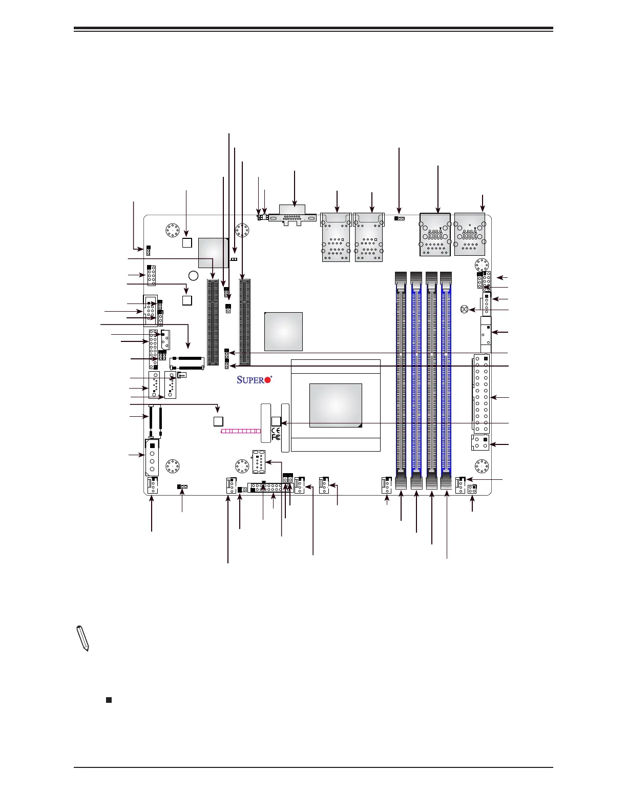
BAR CODE
COM2
DESIGNED IN USA
A2SDV-8C-TLN5F
REV:1.02
JIPMB1
JMD2
JMD1
JTGLED1
JPW1
JPI2C1
JSD1
SRW2
SRW3
SRW4
SRW1
JUIDB
JPL1
1
JWD1
JPG1
JBR1
JPME2
JI2C1
JI2C2
DIMMB1
DIMMB2
DIMMA1
DIMMA2
LED1
1
JD1
JSMB1
JGP1
JBT1
JPH1
JPV1
FANB
JTPM1
JNCSI1
JL1
JRT4
1
JRT3
I-SATA1 I-SATA0
UIDLED1
CM CODE
LEDBMC
eUSB
ON
PWR
JF1
RST X
OH/FF
2
NIC NIC
1 LED
HDD
LED
X
PWR
NMI
ALWAYS POPULATE DIMMx1 FIRST
CPU SLOT6 PCI-E 3.0 X8
CPU SLOT7 PCI-E 3.0 X8
VGA
KEY-M PCIE3/SATA3
KEY-B SATA3/USB3
COM1
LAN1(IPMI_LAN)
LAN5
CPU
USB6(3.0)
USB2/3(3.0)
USB0/1(3.0)
USB 4/5
LAN3
FAN4 FAN3
FAN2 FAN1
LAN4/
LAN2/
FANA
SATA DOM POWER
BT1
JF1
BMC AST2400
JPTG1
JSEL1
Notes:
• See Chapter 2 for detailed information on jumpers, I/O ports, and JF1 front panel connec-
tions. Jumpers/LED indicators not indicated are used for testing only.
• " " indicates the location of Pin 1.
• When JLED1 (Onboard Power LED indicator) is on, system power is on. Unplug the power
cable before installing or removing any components.
Quick Reference
LAN4/5
COM1
USB0/1 (3.0)
LAN1
IPMI
USB2/3 (3.0)
FAN2
FAN3
JL1
JPH1
FANB
USB4/5 eUSB
USB6 (3.0)
DIMMB1
DIMMA1
JPL1
BT1
JTGLED1
JI2C2
JI2C1
JMD2
FAN4
LAN2/3
JPW1
DIMMA2
DIMMB2
JRT3
JSEL1
I-SATA1
JSD1
SRW4
VGA
SRW1
SLOT7
SLOT6
JIPMB1
JWD1
JPI2C1
JPME2
JNCSI1
UIDLED1
LEDBMC
FAN1
JF1
LED1
SRW3
JRT4
FANA
JBR1
JMD1
JUIDB
COM2
JD1
JPG1
JTPM1
SRW2
I-SATA0
JPV1
JBT1
JSMB1
JGP1
JPTG1
 Loading...


