Do you have a question about the Supermicro SC743 Series and is the answer not in the manual?
Manual scope, content, and safety warnings.
Provides contact details for Supermicro headquarters, Europe, and Asia-Pacific.
Brief outline of chassis functions and unpacking instructions.
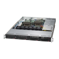
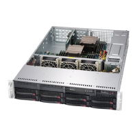
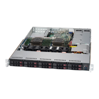
Details on chassis family, drives, cooling, expansion slots, form factor, and dimensions.
Description of control panel buttons and status LEDs.
Identification of features on the front of the chassis.
Identification of features on the rear of the chassis.
Information on obtaining replacement parts and returning for service.
Guidance on setup location, rack, and server precautions.
Safety and environmental factors for rack mounting.
Ensuring electrical safety and proper grounding for rack installations.
Steps to prepare the chassis for rack mounting.
Instructions for removing the tower top cover and chassis feet.
Procedure for identifying and installing rack rails.
Details on identifying rail sections and releasing inner rails.
Steps for attaching inner rails to the chassis.
Instructions for assembling outer rails and rail brackets.
Procedure for sliding the server into the installed rack rails.
Steps for safely removing the chassis from a rack.
Guidance on orienting the control panel for rack mounting.
Visuals of chassis in tower and rack mount modes.
Detailed steps for rotating the control panel module.
Procedures for safely removing power and accessing internal components.
Overview of chassis components.
Details on hot-swap drive bays and their LED indicators.
Instructions for installing and removing hot-swap drive carriers.
Steps for installing and removing 2.5-inch drives into converter trays.
Procedures for removing converter brackets and installing 3.5-inch drives.
Options for configuring 5.25-inch drive bays with peripherals or drives.
Steps for accessing drive trays and installing storage drives.
Instructions for installing peripheral devices like DVD drives.
Details on installing a mobile rack for additional 2.5-inch drives.
Procedure for installing the mobile rack into the chassis.
Steps for installing PCIe expansion cards into the chassis.
Information on chassis cooling system.
Details on chassis fans and how to replace them.
Instructions for installing the air shroud for optimal airflow.
Overview of power supply options and installation.
Steps for installing or replacing the power supply unit.
Detailed specifications for 668W, 900W, and 1200W power supplies.
Industry standard warnings for AC systems, including definitions.
Warning regarding circuit breaker rating for protection.
Safety warning for disconnecting power before servicing.
Warning about installation by trained and qualified personnel only.
Warning regarding installation in restricted access areas.
Warning about potential explosion risk from incorrect battery replacement.
Warning for units with multiple power supply connections.
Warning about hazardous voltage present on the backplane.
Warning to comply with local and national electrical codes.
Warning regarding proper disposal of the product according to laws.
Warning about hazardous moving parts in fan assemblies.
Warning about using correct cables and adapters to prevent malfunction or fire.
Safety guidelines including ESD and general safety for the backplane.
Manual revision and version information for the backplane.
Identification of rear connectors and their silkscreen labels.
Detailed pin definitions for rear connectors.
Chart for SAS port connections in I2C and SGPIO settings.
Configuration details for I2C and SGPIO modes using jumpers.
Explanation of jumper functionality and specific settings.
Description of rear LED indicators and their states.
Identification of front connectors and LEDs.
Mapping of drive numbers to front connectors and LEDs.
Safety guidelines including ESD and general safety for the backplane.
Manual revision and version information for the backplane.
Identification of rear connectors on the backplane.
Detailed pin definitions for rear connectors.
Identification and pin definitions for rear jumpers.
Explanation of jumper functionality and specific settings.
Identification of front connectors and LEDs.
Mapping of drive numbers to front connectors and LEDs.
Safety guidelines including ESD and general safety for the backplane.
Overview and introduction to the SATA-743 backplane.
Identification of front connectors and jumpers on the backplane.
List and identification of front connectors and jumpers.
Detailed pin definitions for front connectors and jumpers.
Locations and pin definitions for front jumpers.
Explanation of jumper functionality and specific settings.
Description of the front LED indicator and its status.
Identification of rear connectors and their corresponding LEDs.
List and identification of rear SATA connectors.
Description of rear LEDs and their activity status.
| Brand | Supermicro |
|---|---|
| Model | SC743 Series |
| Category | Chassis |
| Language | English |