Do you have a question about the Supermicro SC825 Series and is the answer not in the manual?
Describes the purpose and audience of the manual.
Highlights important symbols and safety considerations used throughout the manual.
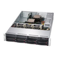
Introduces the SC825 2U chassis and its design.
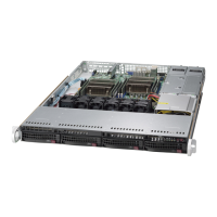
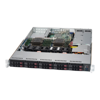
Lists available SC825 chassis models and their specifications.
Details the key features of the SC825 chassis, including drives and slots.
Provides contact information for Supermicro in different regions.
Explains the process for returning products for warranty service.
Introduces industry standard warnings to inform users of potential dangers.
Explains the meaning of the warning symbol and its implications for safety.
Provides crucial instructions to be read before connecting the system to a power source.
Details the protective device rating requirements for short-circuit protection.
Instructs users to disconnect all power sources before internal system access.
States that only trained and qualified personnel should install or service the equipment.
Warns that the unit is intended for installation in areas with restricted access only.
Warns about the danger of explosion from incorrect battery replacement and proper disposal.
Advises to remove all power connections for units with multiple power supplies to de-energize them.
Warns about hazardous voltage or energy present on the backplane during operation.
Mandates that equipment installation must adhere to local and national electrical codes.
States that the product's ultimate disposal must follow all national laws and regulations.
Warns about hazardous moving parts and keeping hands away from fan blades.
Advises using only provided or designated cables/adapters to prevent malfunctions or fire.
Describes the common components included with the SC825 chassis.
Details specific chassis components like Chassis, Backplane, Fans, etc.
Describes the SC825 chassis power supply options and features.
Explains the function of air shrouds in directing airflow for fan efficiency.
Guides users on purchasing replacement parts from authorized distributors.
Introduces LEDs and buttons on the chassis control panel and drive carriers.
Describes the function of the reset and power on/off buttons on the control panel.
Explains the meaning of various LEDs on the control panel and their status.
Explains the green and red LEDs on the drive carriers indicating activity or failure.
Covers steps for installing components and performing chassis maintenance.
Outlines procedures for installation and general maintenance tasks.
Provides a procedure to ensure all power is removed from the system before servicing.
Details the steps to remove the top cover for access to internal components.
Explains how to remove and install hot-swappable hard drives into the chassis.
Describes how to install or replace the slim DVD-ROM drive and front port panel.
Guides on installing the motherboard, including the I/O shield and standoffs.
Explains PCI slot configurations for different SC825 models.
Provides instructions for installing the air shroud to maximize fan efficiency.
Explains the function of system fans and how to replace them.
Details the SC825 chassis power supply models and their auto-switching capabilities.
Provides steps for replacing the power distributor in redundant chassis configurations.
Details the process for replacing or installing the front port panel assembly.
Describes the optional full-face locking front bezel for enhanced security.
Instructs on inspecting the chassis box for damage upon arrival.
Covers selecting a suitable location and preparing for chassis installation.
Lists important warnings and precautions for rack and server installation.
Discusses ambient temperature, airflow, loading, and grounding for rack mounting.
Provides instructions for installing the server into a rack unit using provided rails.
Explains the three sections of the rack rail assemblies (inner, middle, outer).
Details how to release the inner rail from the outer rails for chassis mounting.
Guides on attaching the inner rails to the chassis securely.
Explains how to attach the outer rails to the rack itself.
Describes how to slide the chassis, mounted on inner rails, into the outer rails in the rack.
Lists power supply specifications for various SC825 series models.
Provides essential guidelines to prevent damage from Electrostatic Discharge (ESD).
Outlines general safety practices for handling components and the backplane.
Identifies and illustrates front connectors and SAS ports on the backplane.
Details the pin definitions for various front connectors on the backplane.
Details the SAS ports on the backplane, their numbering, and compatibility.
Provides essential guidelines to prevent damage from Electrostatic Discharge (ESD).
Outlines general safety practices for handling components and the backplane.
Identifies and illustrates the location of rear connectors on the backplane.
Details the pin definitions for various rear connectors on the backplane.
Details the SAS3 ports on the backplane, their numbering, and compatibility.
| Brand | Supermicro |
|---|---|
| Model | SC825 Series |
| Category | Chassis |
| Language | English |