Do you have a question about the Supermicro SC826BE1C-R920LPB and is the answer not in the manual?
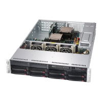
Provides a general overview of the SC826 chassis capabilities and features.
Lists the different SC826 chassis models available from Supermicro.
Details the key features of the SC826 chassis, including drives, power, and cooling.
Provides contact information for Supermicro headquarters, Europe, and Asia-Pacific offices.
Outlines the procedure for returning products for warranty service and RMA authorization.
Explains industry-standard warnings to alert users about potential bodily injury risks.
Provides critical instructions to follow before connecting the system to a power source.
Specifies the required rating for building's short-circuit protection device (60VDC, 20A).
Emphasizes the need to disconnect all power sources before accessing chassis components.
States that only trained and qualified personnel should install, replace, or service the equipment.
Notes that the unit is intended for installation in restricted access areas, requiring special tools or security.
Warns about the danger of battery explosion if replaced incorrectly and advises using manufacturer-recommended types.
Highlights that the unit may have multiple power supply connections and all must be disconnected to de-energize it.
Warns about hazardous voltage or energy present on the backplane during operation and advises caution during servicing.
Mandates that equipment installation must adhere to all applicable local and national electrical codes.
Instructs to handle the ultimate disposal of the product according to all national laws and regulations.
Warns that fans may still be turning after removal and advises keeping hands and objects away from openings.
Provides guidance on using approved wiring terminations for stranded wiring connections.
Stresses the importance of ensuring power is removed from the DC circuit before performing procedures.
Warns of dangerous voltage/energy on DC power terminals and advises replacing covers when not in service.
Introduces the system interface components, including the control panel and status lights.
Describes the function of the power and reset buttons on the chassis control panel.
Explains the status information provided by the various LEDs on the control panel.
Details the status LEDs on the front of each drive carrier, indicating drive activity and failure.
Explains the status LEDs on the rear of the power supply modules.
Provides a procedure to ensure the system is safely de-energized before setup or maintenance.
Details the steps for safely removing the chassis cover for internal access.
Explains how to install 3.5" hot-swappable hard drives into the chassis drive carriers.
Guides the user through the process of installing the motherboard, including standoffs and I/O shield.
Describes how to install low-profile and full-height expansion cards in LP, W, and U model chassis.
Explains how to install the air shroud to concentrate airflow for optimal fan efficiency.
Covers procedures for maintaining system fans, power supplies, and power distributors.
Instructs on inspecting the chassis shipment for any damage upon arrival.
Guides on selecting a suitable, clean, and well-ventilated location for rack installation.
Lists crucial rack and general server precautions for safe installation and operation.
Provides instructions on identifying and mounting the chassis into a rack using provided rail assemblies.
Lists supported cables for the SC826 chassis system, referencing the Supermicro website for more options.
Details the part numbers, types, lengths, and descriptions of included SAS/SATA cables.
Lists compatible cables, including alternate SAS/SATA cables for different motherboard connectors.
Provides essential guidelines for handling backplanes to prevent damage from electrostatic discharge.
Lists general safety practices, such as disconnecting power before component installation or removal.
Informs users that guide images may not exactly match the received product due to PCB revisions.
Introduces the BPN-SAS-826TQ backplane, highlighting its technology and performance.
Identifies and lists the front connectors and SAS ports on the backplane.
Details pin definitions for activity LED headers, expander chips, I2C connectors, and power connectors.
Explains the function and settings of front panel jumpers for backplane operation modification.
Identifies rear connectors and explains the function of rear LED indicators for drive activity and failure.
Provides essential guidelines for handling backplanes to prevent damage from electrostatic discharge.
Lists general safety practices, such as disconnecting power before component installation or removal.
Informs users that guide images may not exactly match the received product due to PCB revisions.
Introduces the BPN-SAS-826A backplane, highlighting its technology and performance.
Identifies and lists the front connectors on the backplane.
Details pin definitions for activity LED headers, expander chips, and I2C connectors.
Explains the function and settings of front panel jumpers for backplane operation modification.
Identifies rear connectors and explains the function of rear LED indicators for drive activity and failure.
Provides essential guidelines for handling backplanes to prevent damage from electrostatic discharge.
Lists general safety practices, such as disconnecting power before component installation or removal.
Informs users that guide images may not exactly match the received product due to PCB revisions.
Introduces the BPN-SAS2-826EL backplane, highlighting its technology and performance.
Compares BPN-SAS2-826EL1 and EL2 backplanes, noting differences in secondary components.
Identifies and lists the front connectors on the BPN-SAS2-826EL1/EL2 backplanes.
Details power connectors, fan connectors, SAS ports, UART, MDIO, and debug connectors.
Explains jumper functions for mode settings, fan monitoring, and buzzer control.
Explains the status indicated by backplane LEDs for overheat, fan failure, Ethernet activity, and power.
Identifies rear SAS connectors and explains the function of rear LEDs for hard drive activity and failure.
Describes single-port and dual-port expanders and their support for cascading.
Explains failover mechanisms for single and dual host bus adapter configurations.
Details failover configurations using RAID controllers or multiple HBAs with MPIO software.
Lists supported cables and the chassis control card for JBOD systems.
Describes cable usage for cascading multiple backplanes from a single HBA in a single channel.
Lists internal and external cables for single HBA configurations with 2-port cascading.
Explains cable usage for cascading multiple backplanes using dual channels with HBAs.
Lists external cables for single HBA configurations.
Describes how to cascade backplanes for faster data access and reduced latency.
Provides essential guidelines for handling backplanes to prevent damage from electrostatic discharge.
Lists general safety practices, such as disconnecting power before component installation or removal.
Informs users that guide images may not exactly match the received product due to PCB revisions.
Introduces the BPN-SAS3-826EL backplane, highlighting its technology and performance.
Compares BPN-SAS3-826EL1 and EL2 backplanes, noting differences in secondary components.
Details power connectors, SAS ports, UART, SDB, and I2C connectors and their pin definitions.
Explains the function of the ACT-LED TEST jumper for activity LED testing.
Explains the status indicated by backplane LEDs for heartbeat, overheat, and power status.
Identifies rear SAS connectors and explains the function of rear LEDs for hard drive activity and failure.
Describes single-port and dual-port expanders and their support for cascading.
Explains failover mechanisms for single host bus adapter configurations.
Details failover configurations using RAID controllers or multiple HBAs.
Lists the supported control card for the BPN-SAS3-826EL series backplane.
Lists common cables for connecting internal HBAs to the backplane.
Describes cable usage for cascading multiple backplanes from a single HBA in a single channel.
Lists internal and external cables for single HBA configurations.
Explains cable usage for cascading multiple backplanes using dual channels with HBAs.
| Form Factor | 2U |
|---|---|
| Material | Steel |
| Power Supply | 920W Redundant |
| Dimensions (H x W x D) | 3.5" x 17.2" |
| Motherboard Support | E-ATX, ATX |
| Backplane | SAS/SATA |
| Front Ports | 2 x USB 3.0 |