EasyManua.ls Logo

Supermicro SC815 series User Manual

Supermicro SC815 series
54 pages
To Next Page IconTo Next Page
Page #1 background imageLoading...
Page #1 background image
SC815 Chassis Series
SC815T-563(CB)(UB) SC815T-330(CB)(UB)
SC815TQ-720(CB)(UB) SC815TQ-710U(B)
SC815TQ-710(B) SC815TQ-710C(B)
SC815TQ-R706WB SC815TQ-R700
(CB)(UB)(WB)
SC815TQ-R600
(CB)(UB)(WB)
SC815TQ-R563
(CB)(UB)
SC815TQ-R500
(CB)(UB)(WB)
SC815TQC-R706
(CB)(WB)
SC815TQC-R605
(CB)(WB)
SC815TQC-R504
(CB)(WB)
SC815S-R650C(V)(B) SC815TQ-R650C(V)(B)
SC815TQ-R650U(V)(B) SC815TQ-R654(CB)
USER’S MANUAL
1.1b
FRONT VIEW
REAR VIEW
Проконсультироваться и купить данное оборудование вы можете в компании «АНД-Системс»
адрес: 125480, г.Москва, ул.Туристская, д.33/1; site: https://andpro.ru тел: +7 (495) 545-4870 email: info@andpro.ru
При обращении используйте промокод AND-PDF и получите скидку.

Table of Contents

Question and Answer IconNeed help?

Do you have a question about the Supermicro SC815 series and is the answer not in the manual?

Supermicro SC815 series Specifications

General IconGeneral
BrandSupermicro
ModelSC815 series
CategoryChassis
LanguageEnglish

Summary

Introduction

Overview

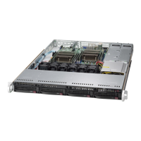
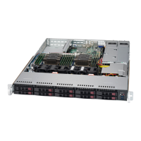
Describes the SC815 1U chassis features and design.

Standardized Warning Statements for AC/DC Systems

About Standardized Warning Statements

Explains industry standard warnings for potential bodily injury.

Warning Definition

Explains the meaning of the "Warning!" symbol and associated hazards.

Power Disconnection Warning

System must be disconnected from all power sources before access.

Equipment Installation

Only trained and qualified personnel should install equipment.

Battery Handling

Warnings regarding battery replacement and disposal.

Backplane Voltage

Hazardous voltage or energy present on the backplane.

DC Power Disconnection

Ensure power is removed from DC circuit before procedures.

Hazardous Voltage or Energy Present on DC Power Terminals

Danger on DC terminals, always replace covers.

Chassis Components

System Interface

Control Panel LEDs

Explains meanings of control panel LED indicators.

Power Supply LEDs and Overheat Indicators

LEDs on power supplies indicating status and temperature.

Chassis Setup and Maintenance

Installing Hard Drives

Steps for installing hard drives into the chassis.

Installing the Motherboard

Steps for installing the motherboard and standoffs.

Expansion Card Setup

How to install expansion cards using riser cards.

Power Supply

Details on power supply units and their replacement.

Rack Installation

Rack Precautions

Safety precautions for mounting and stabilizing racks.

Rack Mounting Instructions

Information on installing the SC815 chassis into a rack unit.

Installing the Chassis into a Rack

Procedure for sliding the chassis into the rack rails.

Appendix A: Power Supply Specifications

SC815 Power Supply Specifications

Lists specifications for various SC815 power supply models.

Appendix B: BPN-SAS-815TQ Backplane Specifications

Front Connector and Pin Definitions

Pin definitions for main power, CD-ROM, JTAG, and upgrade connectors.

Appendix C: BPN-SAS3-815TQ Backplane Specifications

ESD Safety Guidelines

Guidelines for preventing ESD damage to components.

Related product manuals