EasyManua.ls Logo

Supermicro SC815 series - Rear Jumpers and Pin Definitions

Supermicro SC815 series
54 pages
To Next Page IconTo Next Page
To Previous Page IconTo Previous Page
Loading...
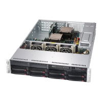
SC815 Chassis Manual
C-6
C-7
Appendix C BPN-SAS3-815TQ Backplane Specications
I
2
C and SGPIO Modes and Jumper Settings
This backplane can utilize I
2
C or SGPIO. SGPIO is the default mode and can be
used without making changes to your jumpers. Use the following settings for I
2
C
mode.
I
2
C Jumpers
Jumper Setting Description
JP33 Pins 2-3 Controller ID
JP34 Pins 1-2:ID#0 Backplane ID
JP40 Open I
2
C Reset SD OUT
JP42 Pins 2-3 Backplane ID SDIN
JP50 Closed I
2
C Reset
SGPIO Jumpers (Default)
Jumper Setting Description
JP33 Pins 1-2 Controller ID
JP34 Pins 1-2:ID#0 Backplane ID
JP40 Closed I
2
C Reset SD OUT
JP42 Pins 1-2 Backplane ID SDIN
JP50 Open I
2
C Reset
C-6 Rear Jumpers and Pin Denitions
Explanation of Jumpers
To modify the operation of the backplane,
jumpers can be used to choose between
optional settings. Jumpers create shorts
between two pins to change the function
of the connector. Pin 1 is identied with
a square solder pad on the printed circuit
board. Note: On two pin jumpers, "Closed"
means the jumper is on and "Open" means
the jumper is off the pins.
Connector
Pins
Jumper
Setting
3 2 1
3 2 1
Figure C-2. Rear Jumpers
JP29
+5V
GNDGND+12V
2
I C
+5V +12V
+5V
+12V
#1
#2
#3
#0
ACT IN
ACT0
ACT1
JTAG UPGRADE
JP29:9071 RST
JP18:BUZZER RESET
ACT2
ACT3
SIDEBAND
M9
M15
JP10
D3
JP18
J8
J7
J6
J5
JP29
JP44
R144
MH2
M46
J9
J10
JP26
JP47
JP46
JP42
JP33
JP34
JP40 JP51
REV 1.00
SAS815TQ
S
UPER
R
JP50
JP18
+5V
GNDGND+12V
2
I C
+5V +12V
+5V
+12V
#1
#2
#3
#0
ACT IN
ACT0
ACT1
JTAG UPGRADE
JP29:9071 RST
JP18:BUZZER RESET
ACT2
ACT3
SIDEBAND
M9
M15
JP10
D3
JP18
J8
J7
J6
J5
JP29
JP44
R144
MH2
M46
J9
J10
JP26
JP47
JP46
JP42
JP33
JP34
JP40 JP51
REV 1.00
SAS815TQ
S
UPER
R
JP50
JP33
JP34
JP40
General Jumpers
Jumper Settings Description
JP18
Open: Enabled
Closed: Disabled
Buzzer Reset
JP29
Open: Default
Closed: Reset
MG 9071 Chip Reset
JP42
JP50
+5V
GNDGND+12V
2
I C
+5V +12V
+5V
+12V
#1
#2
#3
#0
ACT IN
ACT0
ACT1
JTAG UPGRADE
JP29:9071 RST
JP18:BUZZER RESET
ACT2
ACT3
SIDEBAND
M9
M15
JP10
D3
JP18
J8
J7
J6
J5
JP29
JP44
R144
MH2
M46
J9
J10
JP26
JP47
JP46
JP42
JP33
JP34
JP40 JP51
REV 1.00
SAS815TQ
S
UPER
R
JP50

Table of Contents

Related product manuals